Active hydraulic anti-vibration support and an active anti-vibration system incorporating said support

a technology of anti-vibration support and active hydraulic support, which is applied in the direction of machine support, mechanical vibration separation, dynamo-electric machines, etc., can solve the problems of complex and expensive, complex and expensive, and require control means

Inactive Publication Date: 2002-04-02
HUTCHINSON SA
View PDF18 Cites 41 Cited by
  • Summary
  • Abstract
  • Description
  • Claims
  • Application Information

AI Technical Summary

Benefits of technology

Accordingly, the objective of the present invention is to overcome the above-mentioned disadvantages inherent in...

Problems solved by technology

Anti-vibration supports of this type are satisfactory as far as their anti-vibration effect is concerned but have the disadvantage of being complex and expensive and require control means which are in turn complex and expensive.
For reasons of safety, however, certain automotive manufacturers do not wish to use t...

Method used


Image

  • Active hydraulic anti-vibration support and an active anti-vibration system incorporating said support
  • Active hydraulic anti-vibration support and an active anti-vibration system incorporating said support
  • Active hydraulic anti-vibration support and an active anti-vibration system incorporating said support

Examples


Embodiment Construction

The same reference numerals are used in the different drawings to denote identical or similar elements.

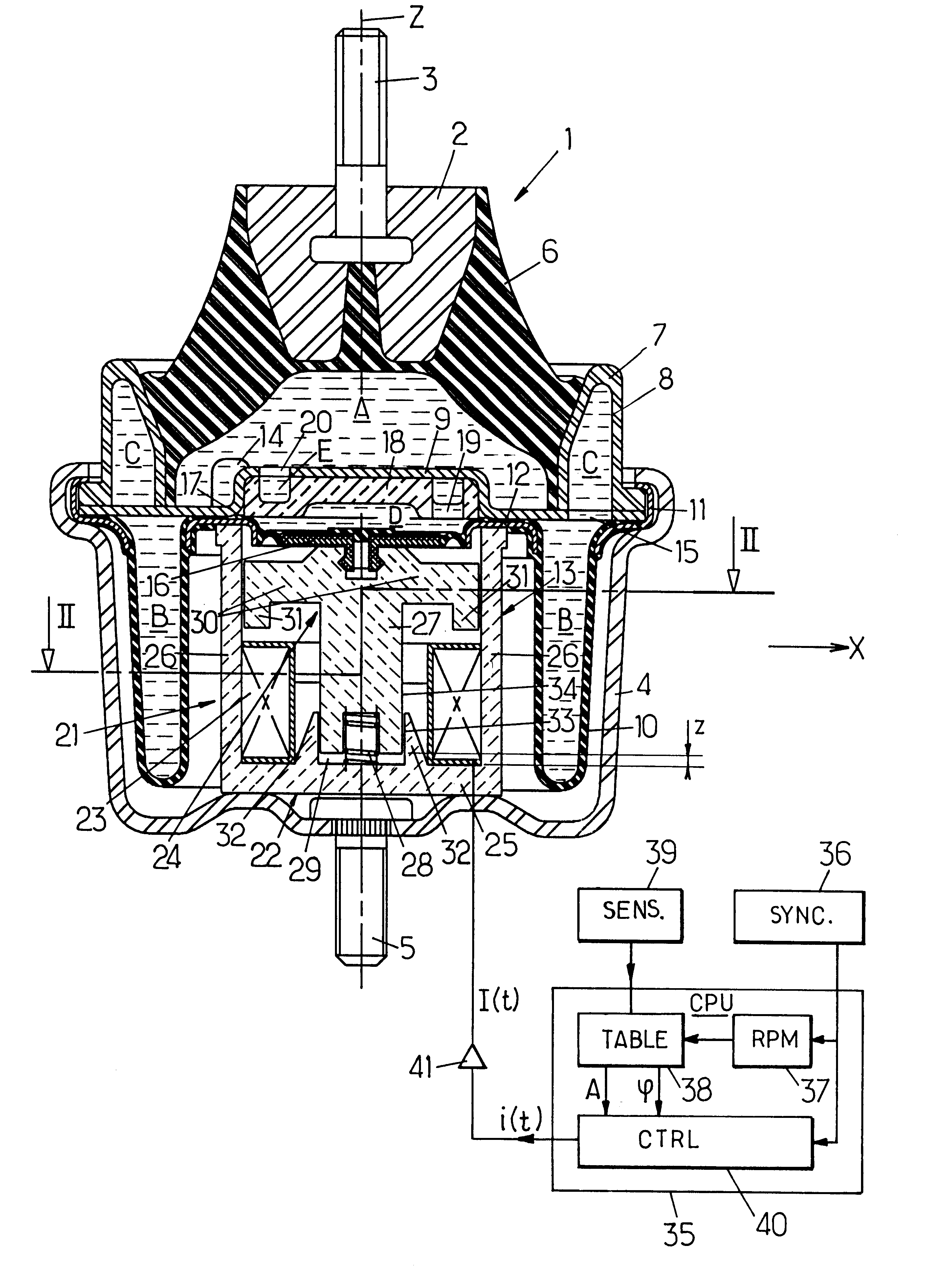
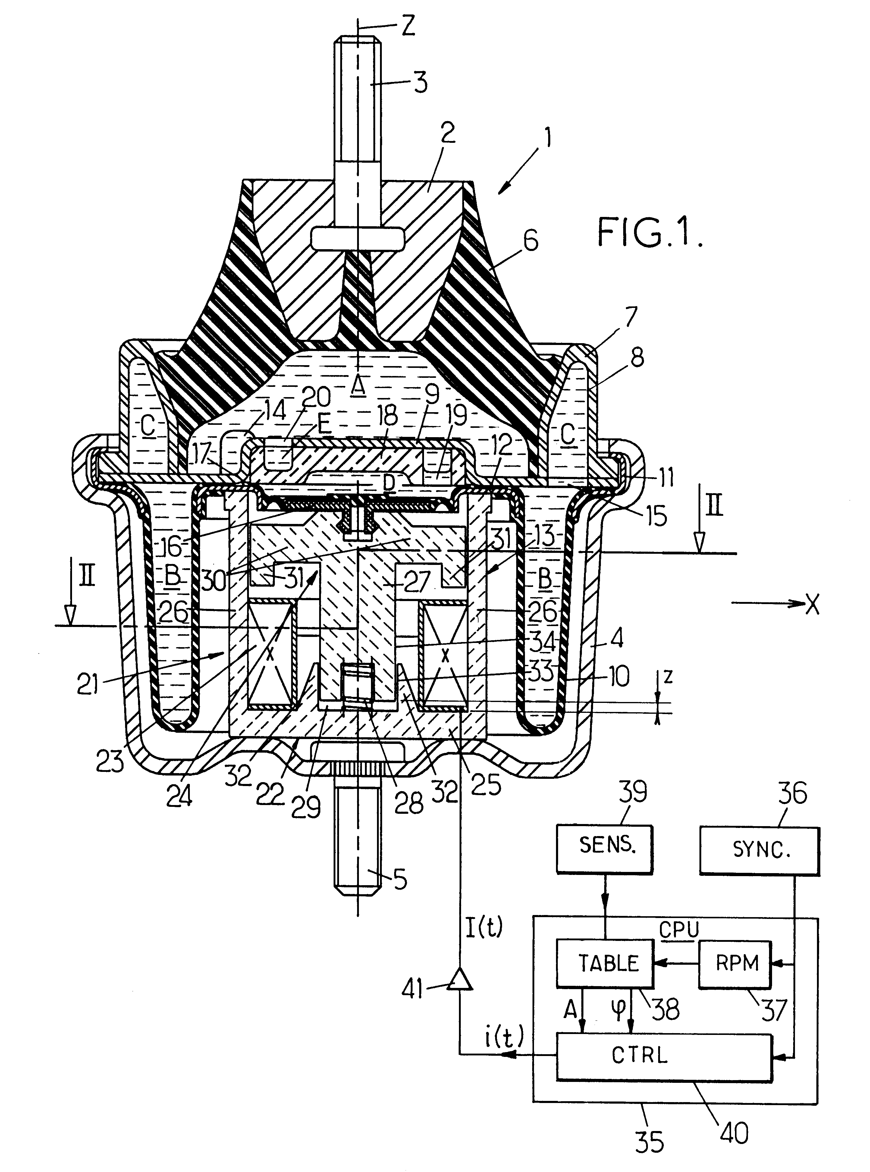
FIG. 1 shows an active hydraulic anti-vibration support 1, which conventionally comprises:

a rigid metal head extended at the top by a pin 3 with a vertical axis Z, designed to be fixed to a part of the engine propulsion group of a motor vehicle, for example,

a rigid metal base 4 which, in the example illustrated, is provided as a cup, the base of which is extended at the bottom by a pin 5 having an axis Z, designed to be fixed to the chassis of the vehicle, for example,

and a thick, elastomer wall 6 of a truncated cone shape which is centred on the axis Z and which flares out in a downward direction from an apex joined to the head 2 down to an annular base which is joined to provide a seal with a rigid metal crown 7 which is hollow, defining a groove 8 open towards the bottom, the thick wall 6 being sufficiently strong to withstand compression so that it can function as a support for...


PUM


Abstract

An anti-vibration support comprising two rigid frames joined to one another by an elastomer body which is applied against a rigid partition to define a hydraulic working chamber linked to a compensating chamber by a throttled passage. The liquid contained in the working chamber is in contact with a piston controlled by an electromagnetic actuator with a proportional electromagnet.

Description

The present invention relates to active hydraulic anti-vibration supports and to active anti-vibration systems incorporating such supports.More specifically, the invention relates to an active hydraulic anti-vibration support designed to be inserted between two rigid elements in a motor vehicle in order to damp and filter vibrations between these two elements, this support comprising at least:first and second rigid frames which can be joined to the first and second rigid elements respectively,an elastomer wall linking the first and second frames to one another and defining a working chamber filled with liquid,a piston which has at least one face in contact with the liquid and which is mounted on the first frame so that it can be displaced in an axis of vibration, this piston being biased towards a rest position by resilient means,an electromagnetic actuator comprising:an electromagnet comprising an electric coil co-operating with a metal frame,a mobile magnetic core which is displac...

Claims


Application Information

Patent Timeline
IPC IPC(8): F16F13/04F16F13/26H02K33/00H02K33/02B60K5/12B06B1/04B06B1/18F16F13/18F16F15/02F16F15/023
CPCH02K33/02F16F13/264
Inventor GENNESSEAUX, ANDRELOUBAT, PATRICEGASTINEAU, JEAN-LUCMENAGER, JOEL
Owner HUTCHINSON SA
Why Eureka
Try Eureka