Electronically controlled fluid coupling device

a fluid coupling device and electronic control technology, applied in the direction of fluid couplings, couplings, valve operating means/release devices, etc., can solve the problems of system resonance problem, actuator limiting the use of narrow package applications, and the length of tether for front mount actuators becomes a limiting factor

Inactive Publication Date: 2006-08-01
BORGWARNER INC
View PDF15 Cites 42 Cited by
  • Summary
  • Abstract
  • Description
  • Claims
  • Application Information

AI Technical Summary

Benefits of technology

[0009]The present invention enables a viscous fan drive with a front-mounted fan and electrical actuation without a tethered harness. The device of the present invention combines an inverted viscous clutch, a drive pulley and a split electromagnetic actuator resulting in a purely mechanical package that provides several advantages over existing engine-driven electronically managed viscous fan drives. An inverted clutch is one where the conventional clutch is essentially flipped around such that the central shaft is the output shaft while the finned members are the input.
[0010]In this configuration, the electrical portion of the actuator is not physically attached to the fan drive but rather is mounted to a stationary member of the drive pulley. The remaining actuator components are integral to the fan drive and as a result the fan drive itself has purely mechanical parts. The arrangement allows for fast response times to engage or disengage the clutch and also allows for open loop control of the electrical actuation.

Problems solved by technology

The length of tether for front mount actuators becomes a limiting factor for large fan applications and the axial length of the rear mount actuator limits the use from narrow package applications.
Durability issues with the tether and higher fuel economy requirements forced the heavy-duty industry to switch to pneumatic on-off friction clutches with no tether (air supply coming through the center of the mounting bracket-pulley subassembly).
However, in some light duty gas engine applications where the fan clutch is driven by the waterpump, a system resonance problem exists caused by numerous factors including mass and cg of the fan drive.

Method used


Image

  • Electronically controlled fluid coupling device
  • Electronically controlled fluid coupling device
  • Electronically controlled fluid coupling device

Examples


Embodiment Construction

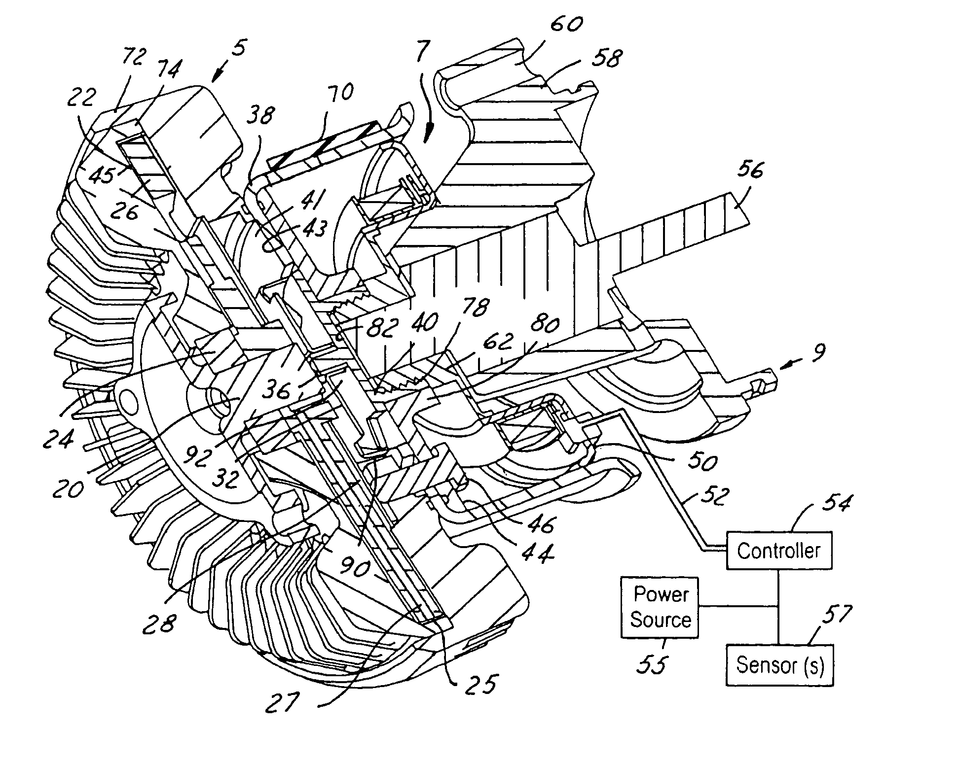
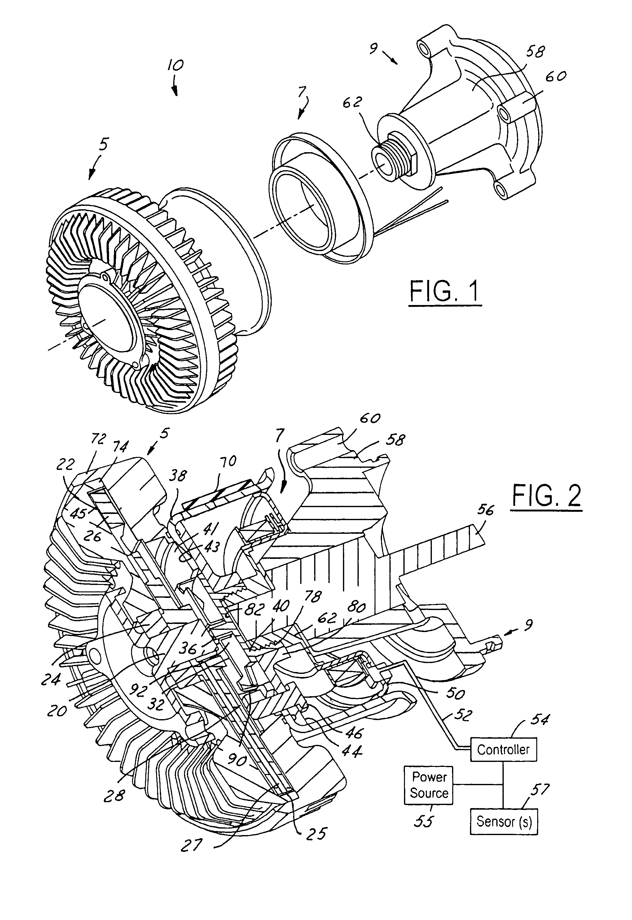
[0015]Referring now to the drawings, which are not intended to limit the invention, FIGS. 1–3 illustrates one preferred form of a fluid coupling device 10 (“viscous fan drive”) of a type utilizing the present invention. As best shown in FIG. 1, the fluid coupling device consists of three major subassemblies, including a fan drive subassembly 5, an electromagnet subassembly 7, and a waterpump subassembly 9. The waterpump subassembly 9, shown here as an engine-mounted waterpump subassembly 9 driven by a crankshaft pulley system, could also be a stand-alone bracket-pulley subassembly. As shown in FIG. 2, the electromagnet subassembly 7 is mounted to the stationary waterpump housing and the fan drive subassembly 5 mounts to the waterpump subassembly 9.

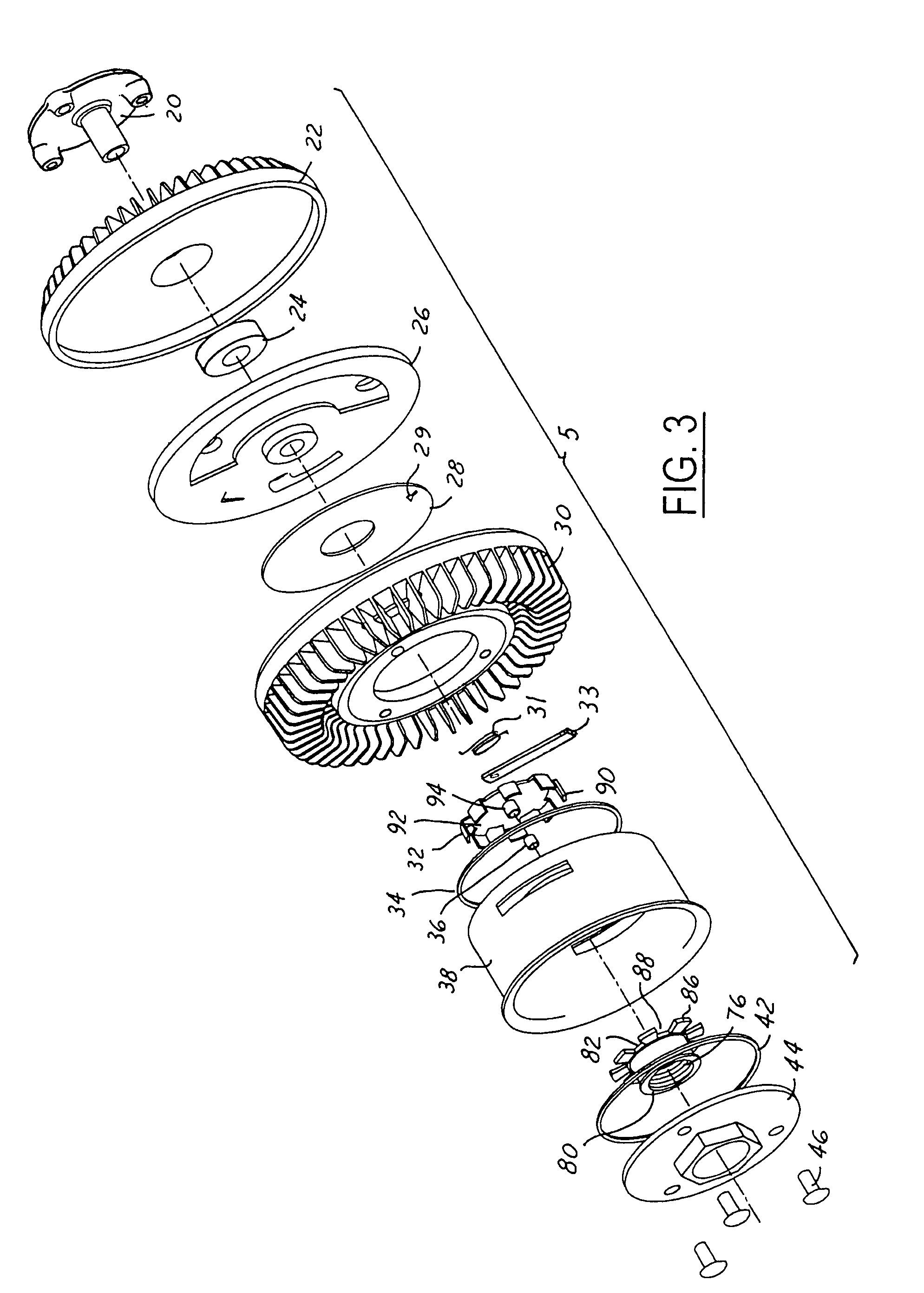
[0016]As best shown in FIGS. 2 and 3, the fan drive subassembly 5 includes an output shaft 20, a body 22, a ball bearing 24, a rotor 26, a reservoir plate 28 having a fill port 29, a cover 30, a torsion spring 31 an armature valve subassem...


PUM


Abstract

An electronically-controlled fluid coupling device having a front mounted fan and electrical actuation without a tethered harness. The fluid coupling device combines an inverted viscous clutch, drive pulley and a split electromagnetic actuator package. In this arrangement, the electrical portion of the split electromagnetic actuator is not physically attached to the fan drive, but is instead mounted to a stationary member. The remaining actuator components are integral to the fan drive and are composed of only mechanical parts. The inverted clutch arrangement having remote electronic control allows three output modes: engaged, partially engaged, or disengaged.

Description

TECHNICAL FIELD[0001]The invention relates generally to fan drive systems and more specifically to an electronically controlled fluid coupling device.BACKGROUND ART[0002]The present invention relates to fluid coupling devices of the type including both fluid operating chamber and a fluid reservoir chamber, and valving which controls the quantity of fluid in the operating chamber.[0003]Although the present invention may be used advantageously in fluid coupling devices having various configurations and applications, it is especially advantageous in a coupling device of the type used to drive a radiator cooling fan of an internal combustion engine, and will be described in connection therewith.[0004]Fluid coupling devices (“fan drives”) of the viscous shear type have been popular for many years for driving engine cooling fans, primarily because their use results in substantial saving of engine horsepower. The typical fluid coupling device operates in the engaged, relatively higher spee...

Claims


Application Information

Patent Timeline
Patent Type & Authority Patents(United States)
IPC IPC(8): F16D35/02F16K31/06
CPCF16D48/06F16D35/024F16D48/064F16D2500/1022F16D2500/10487F16D2500/3064F16D2500/3067F16D2500/7027F16D2500/70418F16D2500/7109
Inventor BOYER, RICK L.
Owner BORGWARNER INC
Why Eureka
Try Eureka