Apparatus for threading a tape from a cartridge

a technology of cartridge magnetic tape drive and cartridge head, which is applied in the direction of record information storage, printing, instruments, etc., can solve the problems of affecting the rotational value and affecting the accuracy of the rotator cam

Active Publication Date: 2005-12-22
NEC CORP
View PDF10 Cites 6 Cited by
  • Summary
  • Abstract
  • Description
  • Claims
  • Application Information

AI Technical Summary

Benefits of technology

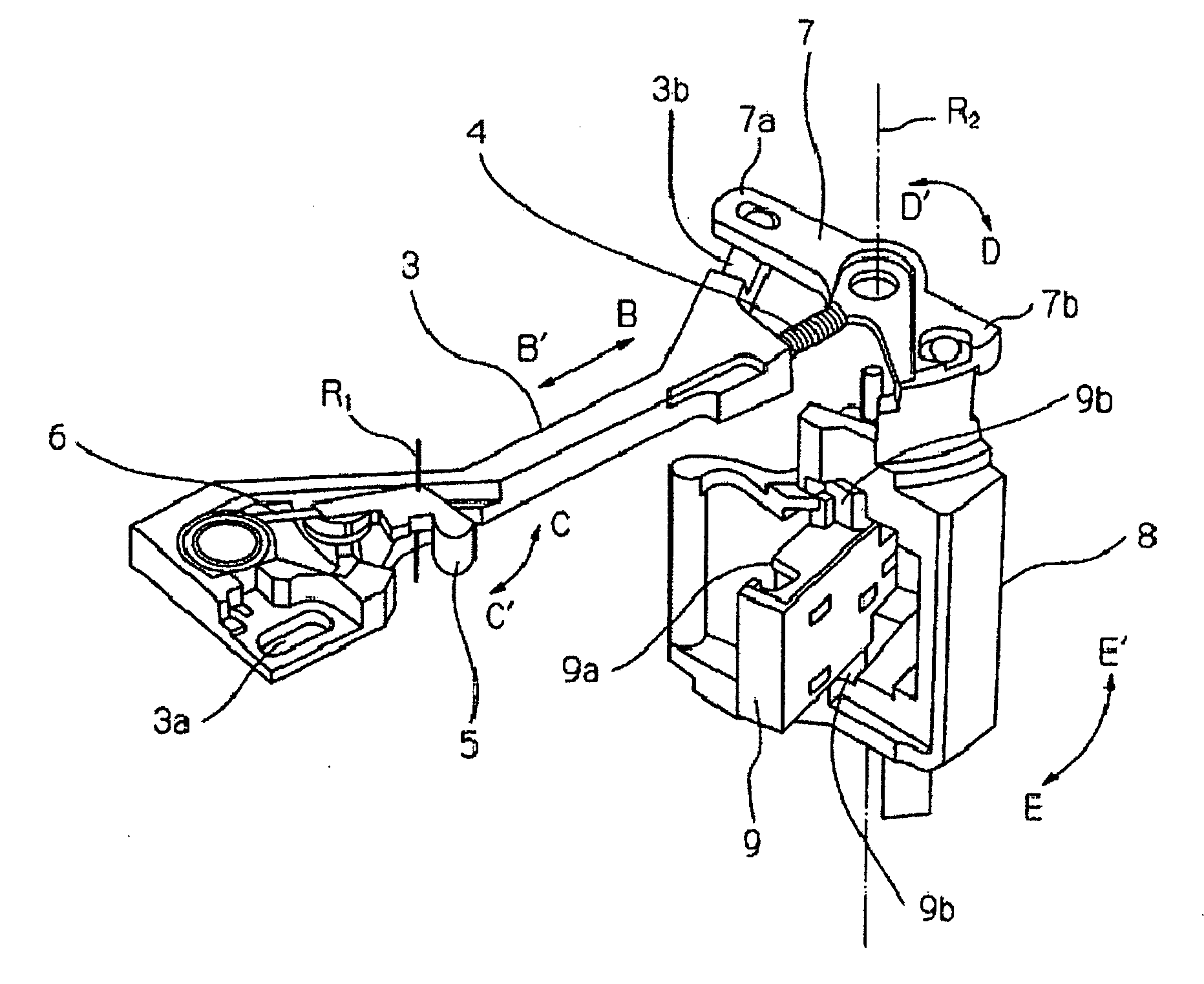
[0040] According to the above configuration, even when the loader cam gear excessively rotates for any reason or movement of the rod is interrupted because a stack occurs when capturing the leader pin, the excessive-pressure absorbing portion is elastically deformed and thereby the loader cam gear can rotate in a certain range while holding the mechanism components such as the rod, rotator lever, rotator, and leader block in the present position. Because an excessive force working on the mechanism components is thus absorbed by the excessive-pressure absorbing portion being elastically deformed, it is possible to securely prevent the mechanism components from breaking. Moreover, it is possible to realize a design for excessively rotating the loader cam gear, delicate adjustment of the rotation value of the loader cam gear is unnecessary and moreover, it is possible to solve the problem that miscapture of the leader pin occurs due to excessive or insufficient rotation of the loader cam gear.

Problems solved by technology

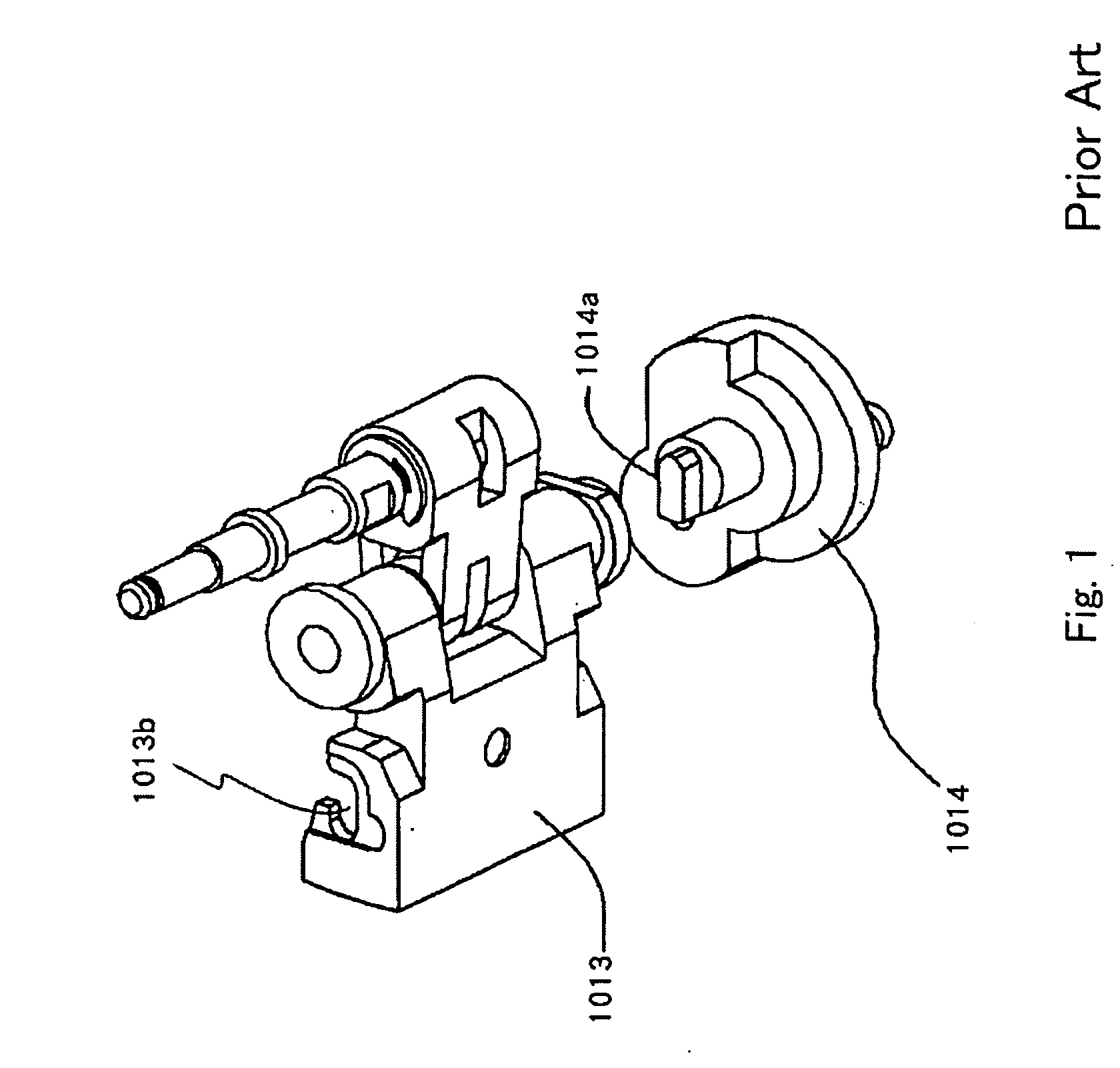
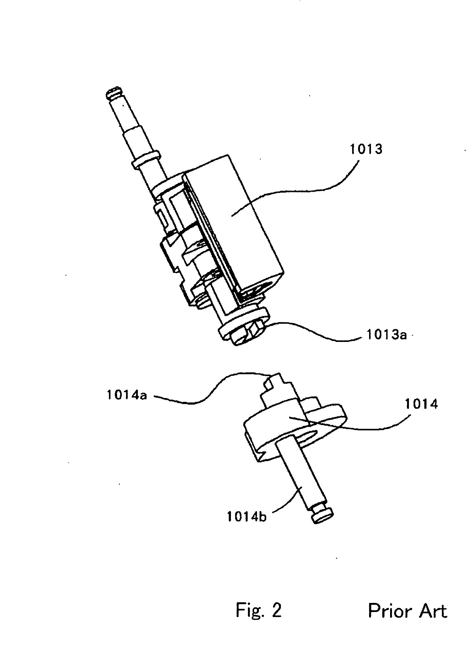
Therefore, miscapture of the leader pin may occur due to excessive or insufficient rotation of the leader block 1013 depending on operation states of these mechanisms.
Therefore, delicate adjustments of the rotation stop position of the loader cam gear 2005 and the rotational value of the rotator cam 2007 at the time of capture become completely unnecessary.
Therefore, in the case of the configuration in the above Patent Document 2, it is difficult to downsize an apparatus.

Method used


Image

  • Apparatus for threading a tape from a cartridge
  • Apparatus for threading a tape from a cartridge
  • Apparatus for threading a tape from a cartridge

Examples


Embodiment Construction

[0080] Then, exemplary embodiments of the present invention are described below by referring to the accompanying drawings.

[0081]FIGS. 11A and 11B are illustrations showing a major portion of a configuration of a magnetic tape cartridge used for a cartridge magnetic tape drive. FIG. 11A is a local sectional view of the major portion from the side of the cartridge and FIG. 11B is an illustration showing the major portion from a face on which there is a takeout port of a cartridge magnetic tape.

[0082] A cartridge 1 includes a magnetic tape 1a and a leader pin 1b is set to the front end of the magnetic tape 1a. The leader pin 1b is engaged with pin fixing grooves 1c formed at the both sides of the inner wall of the cartridge 1 toward the illustrated arrow direction.

[0083]FIG. 12 is a perspective view of a cartridge magnetic tape drive of the exemplary embodiment by removing a casing portion from the drive. FIG. 13 is a top view of the cartridge magnetic tape drive of the exemplary em...


PUM

PropertyMeasurementUnit
pressureaaaaaaaaaa
magneticaaaaaaaaaa
tensionaaaaaaaaaa

Abstract

An apparatus for threading a tape from a cartridge is to be provided. In the apparatus, a leader block rotates to capture a coupling element of the tape, a rod linearly moves to rotate the leader block, and a loader cam gear moves the rod.

Description

BACKGROUND OF THE INVENTION [0001] 1. Field of the Invention [0002] The present invention relates to a leader block rotating mechanism of a cartridge magnetic tape drive. [0003] 2. Description of the Related Art [0004] For example, Patent Document 1 discloses a leader block rotating mechanism of a cartridge magnetic tape drive which captures or releases a leader pin of a magnetic tape by rotating a leader block. [0005]FIGS. 1 and 2 show a configuration of a conventional leader block rotating mechanism disclosed in Patent Document 1 and FIGS. 3 and 4 show its working principle. FIG. 3 shows the leader block rotating mechanism from the upside and FIG. 4 shows it from the downside. Moreover, FIG. 5 shows a schematic configuration of the conventional cartridge magnetic tape drive disclosed in Patent Document 1. [0006] As shown in FIGS. 1 and 2, the conventional leader block rotating mechanism is engaged with a protrusion 1014a of a retractor table 1014 on which a groove 1013a of a leade...

Claims


Application Information

Patent Timeline
Patent Type & Authority Applications(United States)
IPC IPC(8): G11B15/66G11B15/67
CPCG11B15/673G11B15/672
Inventor SHIMANUKI, HIROYUKI
Owner NEC CORP
Why Eureka
Try Eureka