System and method for controlling range of successful interrogation by RFID interrogation device

a radiofrequency identification and interrogation device technology, applied in the direction of burglar alarm mechanical actuation, burglar alarm by hand-portable objects removal, instruments, etc., can solve the problem of inflexible placement, high cost of barriers, and added complexity of high-rate modulation imposed on transmitters, so as to minimize the chance of reader reading tags in other locations

Inactive Publication Date: 2005-12-22
WJ COMM
View PDF7 Cites 79 Cited by
  • Summary
  • Abstract
  • Description
  • Claims
  • Application Information

AI Technical Summary

Benefits of technology

[0010] The present invention is directed to controlling a range of successful interrogation by an RFID reader so that tags located in a specific physical area are likely to be successfully interrogated by the reader while the chance of the reader reading tags in other locations are minimized. In one embodiment of the present invention, a plurality of delineation RFID tags with known unique identifying numbers are placed in an areas of interest or wanted region, and the reader is characterized to determine an optimal setting for at least one transmission parameter based on responses from the delineation RFID tags and a predetermined figure of merit.
[0011] More specifically, in some embodiments a system is provided for reading an RFID tag in a defined region while reducing the possibility of reading other RFID tags outside the region, comprising an RFID reader at a fixed location in or near the region, the RFID reader capable of adjusting at least one associated transmission parameter. A plurality of delineation RFID tags each having a known and unique identification are placed at specified locations in the region, an...

Problems solved by technology

Such barriers are expensive and inconvenient, as they must be either strongly absorbing or reflecting, and sufficiently large relative to the wavelength of the RF signals in question to minimize diffractive bypass of the obstacle.
However, this scheme suffers from the added complexity of a high-rate modulation imposed on the transmitter, and inflexibility in the placement of the rejected region relative to ...

Method used


Image

  • System and method for controlling range of successful interrogation by RFID interrogation device
  • System and method for controlling range of successful interrogation by RFID interrogation device
  • System and method for controlling range of successful interrogation by RFID interrogation device

Examples


Embodiment Construction

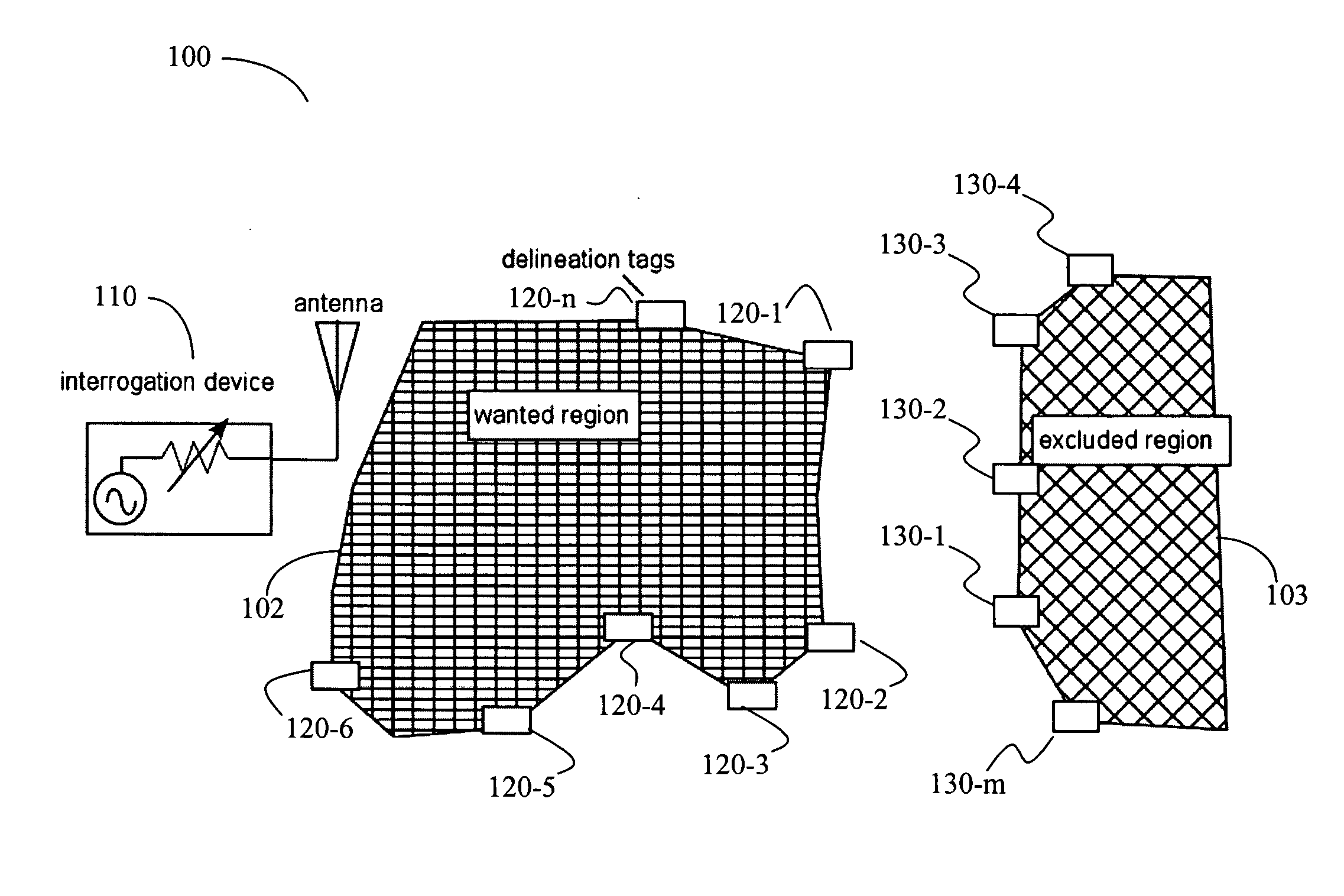
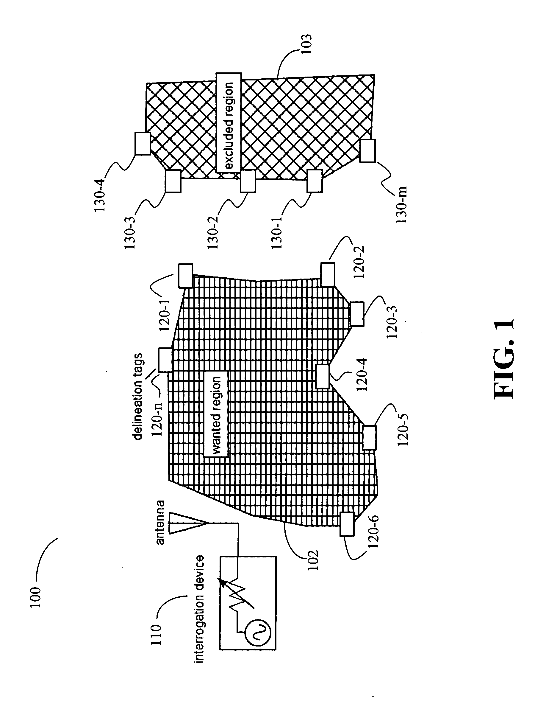
[0022]FIG. 1 illustrates a system 100 for controlling a range of successful interrogation by an RFID reader according to one embodiment of the present invention. As shown in FIG. 1, system 100 generally comprises an RFID reader 110 and a plurality of delineation RFID tags 120 placed at specified locations in a region of interest or wanted region 102. The wanted region 102 represents a region for intentional RFID interrogation. For example, in the situation of a tollgate, the wanted region 102 can be an area in front of the tollgate for cars to pass through while their toll meter is being read by an RFID reader installed at the tollgate. The plurality of delineation RFID tags 120 includes RFID tags 120-1, 120-2, . . . , and 120-n, where n is a positive integer greater than 1. Each delineation RFID tag 120 can be a conventional RFID tag having a known and unique identification number. The delineation RFID tags 120 can be placed along the boundary of wanted region 102, as shown in FIG....


PUM


Abstract

The present invention is directed to control an range of successful interrogation by an RFID reader so that tags located in a specific physical area are likely to be successfully interrogated by the reader while the chance of the reader reading tags in other locations are minimized. In one embodiment of the present invention, a plurality of delineation RFID tags with known unique identifying numbers are placed in an areas of interest or wanted region, and the reader is characterized to determine an optimal setting for at least one transmission parameter based on responses from the delineation RFID tags and a predetermined figure of merit.

Description

CROSS REFERENCE TO RELATED APPLICATIONS [0001] The present application claims the benefit of and priority to U.S. Provisional Patent Application No. 60 / 547,495 filed on Feb. 24, 2004, the entire disclosure of which is hereby incorporated by reference in its entirety.FIELD OF THE INVENTION [0002] The present invention relates in general to interrogation of radio-frequency identification (RFID) transponders, and particularly to a method and system for interrogating ‘passive’ RFID transponders while controlling a range of successful interrogation. BACKGROUND OF THE INVENTION [0003] RFID technologies are widely used for automatic identification. A basic RFID system includes an RFID tag or transponder carrying identification data and an RFID interrogator or reader that reads and / or writes the identification data. An RFID tag typically includes a microchip for data storage and processing, and a coupling element, such as an antenna coil, for communication. Tags may be classified as active ...

Claims


Application Information

Patent Timeline
IPC IPC(8): G06K7/00H04Q5/22
CPCG06K7/10019G06K7/0008
Inventor MRAVCA, JIMDOBKIN, DANIEL
Owner WJ COMM
Why Eureka
Try Eureka