Electronic component cooling apparatus

Inactive Publication Date: 2005-12-22
SANYO DENKI CO LTD
View PDF19 Cites 20 Cited by
  • Summary
  • Abstract
  • Description
  • Claims
  • Application Information

AI Technical Summary

Benefits of technology

[0035] The two liquid tanks can be so arranged that the uppermost sub-chamber in one of the two tanks is situated higher than the uppermost sub-chamber in the other tank. Also, the uppermost sub-chamber of the one tank situated higher than the uppermost sub-chamber of the other tank is formed

Problems solved by technology

As an amount of heat generated by electronic components increases, however, a problem arises that

Method used


Image

  • Electronic component cooling apparatus
  • Electronic component cooling apparatus
  • Electronic component cooling apparatus

Examples


Embodiment Construction

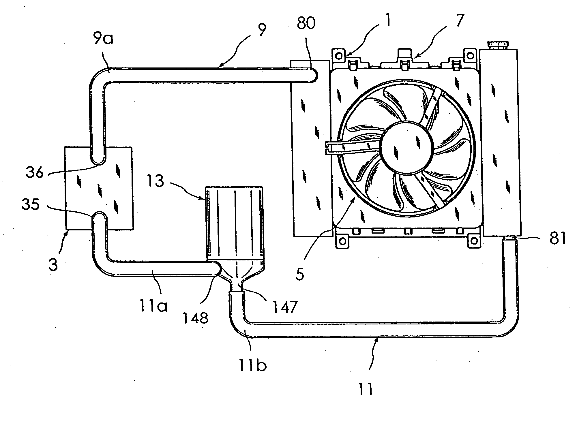
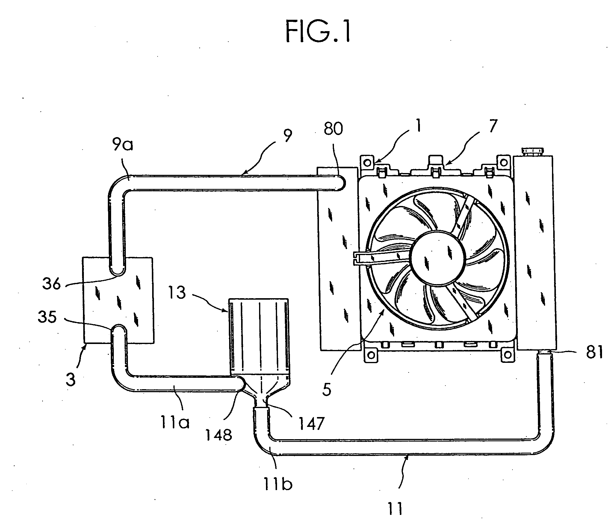
[0049] Now, by referring to the accompanying drawings, one embodiment of an electronic component cooling apparatus according to the present invention will be described in detail. FIG. 1 is a plan view showing a construction of embodiment of an electronic component cooling apparatus 1 according to the present invention. The electronic component cooling apparatus 1 has a water-cooled heat sink 3 having a coolant path therein, a radiator 7 cooled by a motor-driven fan 5, and a motor-driven pump 13 for giving a moving energy to the coolant in order to circulate the coolant between the heat sink 3 and the radiator 7.

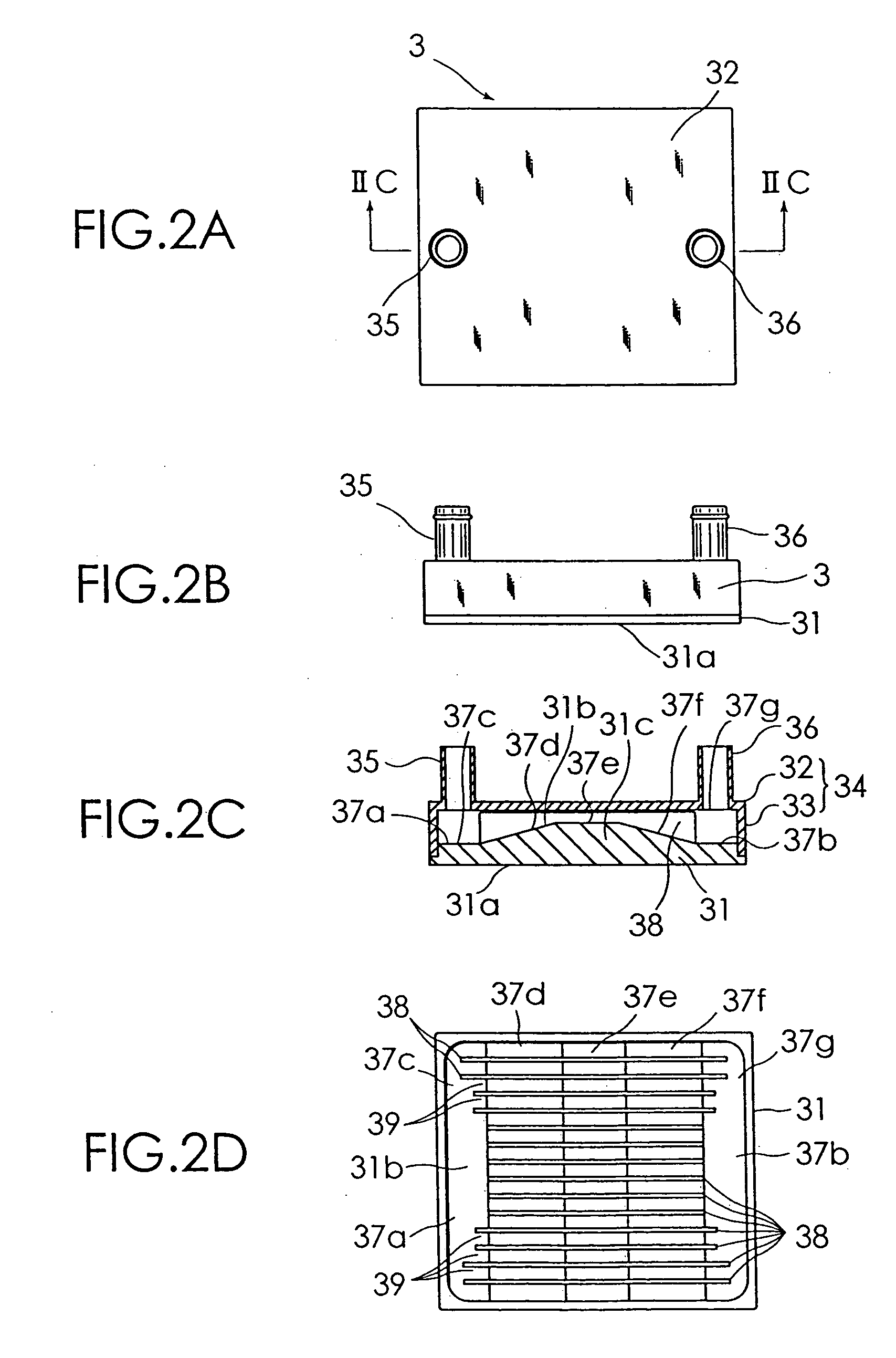
[0050] The heat sink 3 has an electronic component mounting surface for mounting electronic components, such as a CPU, to be cooled. Also the heat sink 3 has a coolant path, with a coolant inlet (a cylindrical member 35) and a coolant outlet (a cylindrical member 36), through which a liquid coolant flows to forcibly cool the electronic component mounting surface. The radiato...


PUM


Abstract

An electronic component cooling apparatus comprises a so-called water-cooled heat sink, a radiator to be cooled by a motor-driven fan, first and second coolant paths for circulating a coolant between the heat sink and the radiator, and a motor-driven pump for giving a moving energy to the coolant. A plurality of engaging pieces of the motor-driven fan and a plurality of engaged portion of the radiator are engaged to connect the motor-driven fan and the radiator.

Description

BACKGROUND OF THE INVENTION [0001] The present invention relates to an electronic component cooling apparatus for forcibly cooling electronic components such as microcomputers and to a motor-driven pump and a radiator used in the electronic component cooling apparatus. [0002] Most of conventional electronic component cooling apparatuses, as disclosed in U.S. Pat. No. 5,519,574, have a combination of a heat sink having a plurality of radiation fins on a surface of a base plate and a motor-driven fan for forcibly cooling these fins and the surface of the base plate. [0003] As an amount of heat generated by electronic components increases, however, a problem arises that simply air-cooling the heat sink cannot cool the electronic components down to a sufficient degree. SUMMARY OF THE INVENTION [0004] The prevent invention has been made to solve the problems described above. Accordingly, an object of the present invention is to provide an electronic component cooling apparatus that can c...

Claims


Application Information

Patent Timeline
IPC IPC(8): F01P5/02F01P3/12F01P5/04F28D1/053H01L23/473H02K7/14H02K21/22H05K7/20
CPCF04D13/0673F04D29/588F28D1/05366F28D2021/0031H01L23/473H01L2924/0002F04D13/0633H01L2924/00
Inventor IIJIMA, MASAYUKIMIYAZAWA, MASASHIUENO, KOUJI
Owner SANYO DENKI CO LTD
Why Eureka
Try Eureka