Channel control apparatus and channel control method

a control apparatus and channel technology, applied in the field of channel control apparatus and channel control method, can solve the problems of difficult operation, complex processing in the nms b>220/b>, and cannot be applied to a network structure such as n:1

Inactive Publication Date: 2005-12-22
FUJITSU LTD
View PDF11 Cites 23 Cited by
  • Summary
  • Abstract
  • Description
  • Claims
  • Application Information

AI Technical Summary

Benefits of technology

[0040] It is an object of the present invention to solve at least the problems in the conventional technology.
[0041] A channel control apparatus according to an aspect of the present invention is arranged at a node on a source as a transmission side and at a node on a sink as a reception side, and changes a bandwidth of virtual concatenation using link capacity adjustment scheme information between the node on the source and the node on the sink. The channel control apparatus includes an information adding unit that adds additional information for adjustment of a member of the virtual concatenation, to the link capacity adjustment scheme information; and a virtual concatenation/link capacity adjustment scheme main controller. The virtual concatenation/link capacity adjustment scheme main controller transmits the link capacity adjustment scheme information including the additional information added, to a partner node of either one node on the source and the sink, and adjusts a member of the virtual concatenation based on the additional information added to the link capacity adjustment scheme information, when receiving the link capacity adjustment scheme information including the additional information, from the partner node.
[0042] A channel control method according to another aspect of the present invention is a method of changing a bandwidth of virtual concatenation between a node on a source as a transmission side and a node on a sink as a reception side using link capacity adjustment scheme information. The channel control method includes adding additional information for adjustment of a member of the virtual concatenation, to the link

Problems solved by technology

However, the LCAS is configured to be used in point-to-point topology, and therefore, it cannot be applied to a network structure such as N:1.
Therefore, even if reception exceeds the reception capacity of the sink, the sink cannot determine or control any particular member of any particular VCG from

Method used


Image

  • Channel control apparatus and channel control method
  • Channel control apparatus and channel control method
  • Channel control apparatus and channel control method

Examples


Embodiment Construction

[0062] Exemplary embodiments of a channel control apparatus and a channel control method according to the present invention are explained in detail below with reference to the accompanying drawings.

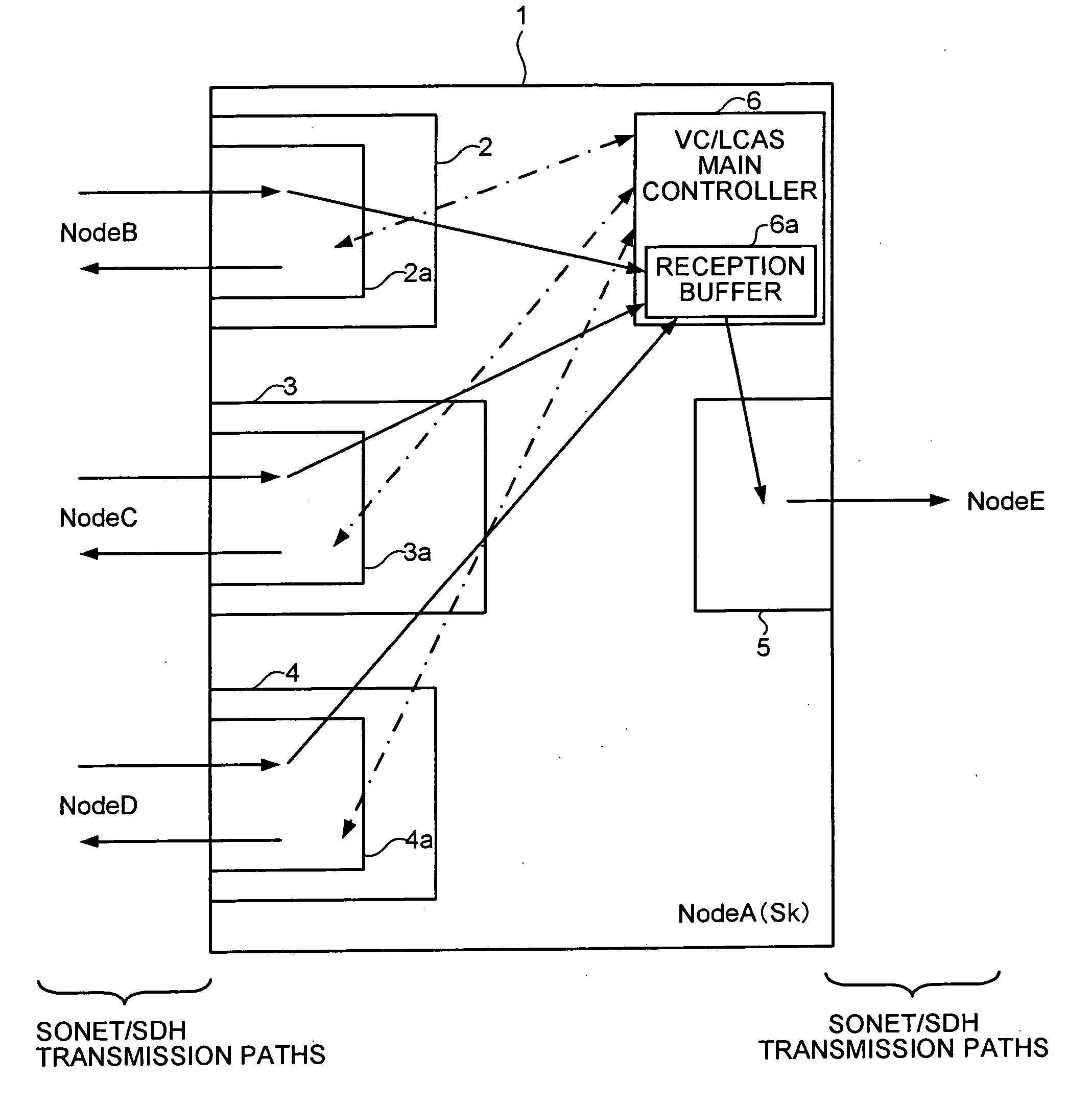
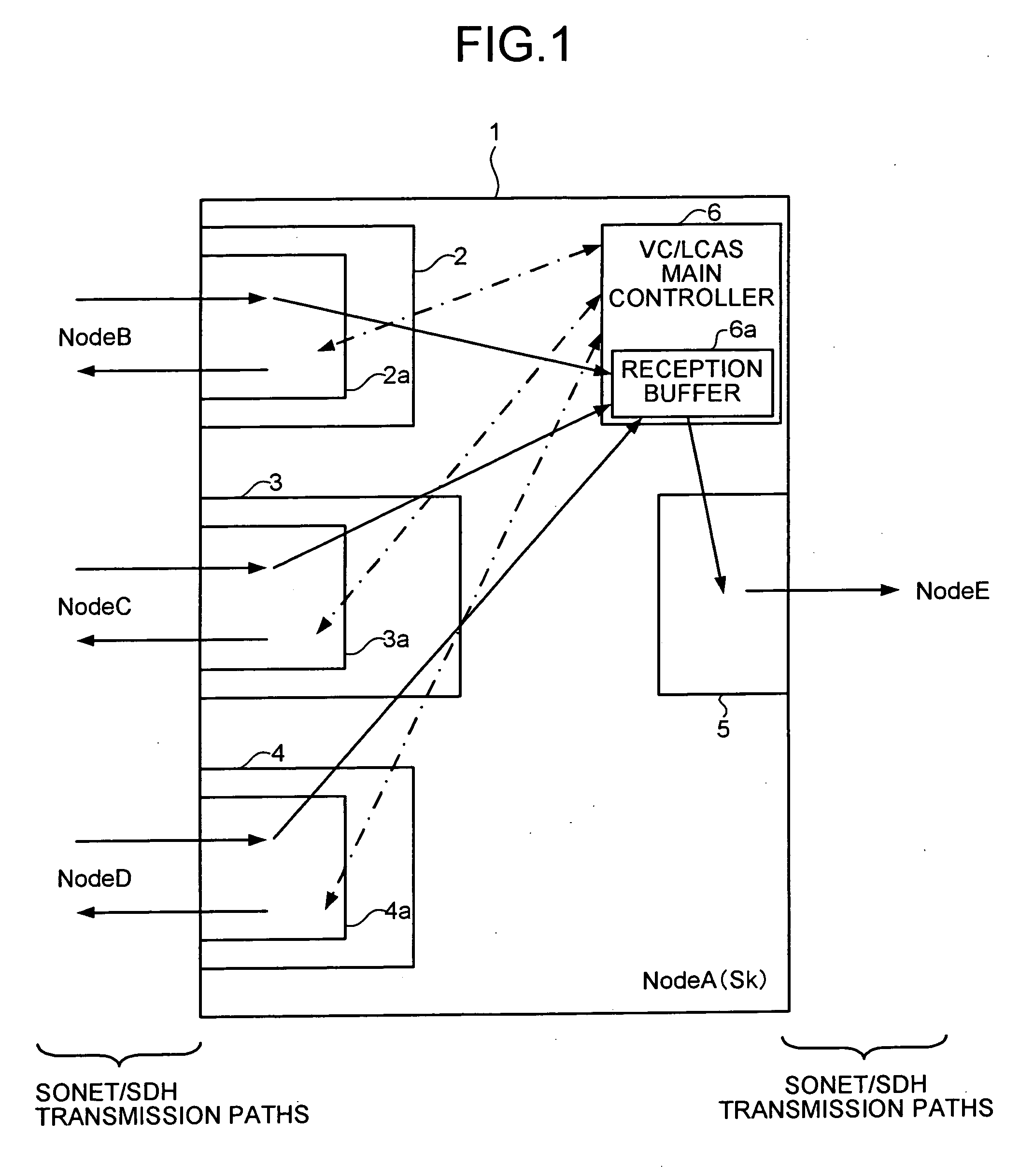
[0063]FIG. 1 is a block diagram of a configuration of a sink (Sk) of the channel control apparatus according to the present invention. An example of a channel control apparatus 1 arranged at a node (NodeA) is shown in FIG. 1.

[0064] The channel control apparatus 1 includes a plurality of I / F cards 2, 3, and 4 that receive data transmitted from nodes (NodeB, NodeC, and NodeD) on a plurality of sources (So). The I / F cards 2, 3, and 4 include LCAS controllers 2a, 3a, and 4a, respectively. Data received by the I / F cards 2, 3, and 4 is collected in the channel control apparatus 1 and is transmitted to another node (NodeE) through an I / F card 5. Each of nodes (NodeB, NodeC, NodeD, or NodeE) transmits and receives data to and from the channel control apparatus 1 through a transmission path. The...


PUM


Abstract

A channel control apparatus is arranged in a plurality of nodes on a source as a transmission side and at a node on a sink as a reception side, and changes a bandwidth of virtual concatenation (VC) between the nodes on the source and the sink using link capacity adjustment scheme (LCAS) information. The channel control apparatus includes a VC/LCAS main controller that sets member use-request information for the VC or member usable information for the VC in the LCAS information, and changes the member of the VC between the nodes on the source and the node on the sink.

Description

CROSS-REFERENCE TO RELATED APPLICATIONS [0001] This application is based upon and claims the benefit of priority from the prior Japanese Patent Application No. 2004-183092, filed on Jun. 21, 2004, the entire contents of which are incorporated herein by reference. BACKGROUND OF THE INVENTION [0002] 1) Field of the Invention [0003] The present invention relates to a technology for controlling network channels by using information according to link capacity adjustment scheme protocol. [0004] 2) Description of the Related Art [0005] There are channel control apparatuses that control network channels. Some of them control channels using information according to the Link Capacity Adjustment Scheme (LCAS) protocol. The LCAS is a protocol used to dynamically change the capacity (bandwidth) of Virtual Concatenation (VC). By dynamically allocating channels using the VC and the LCAS, data for a plurality of protocols (e.g., Gigabit Ethernetâ„¢ and ES COM) can be concurrently transmitted to chann...

Claims


Application Information

Patent Timeline
IPC IPC(8): H04J3/12H04L12/46H04L45/243H04L47/76
CPCH04J3/12H04L12/4641H04J2203/0094H04J2203/0069
Inventor HONDA, TAKASHI
Owner FUJITSU LTD
Why Eureka
Try Eureka