

Pluggable optical transceiver with highly shielded structure
- Summary
- Abstract
- Description
- Claims
- Application Information
AI Technical Summary
Benefits of technology
Problems solved by technology
Method used
Image

Examples
Embodiment Construction
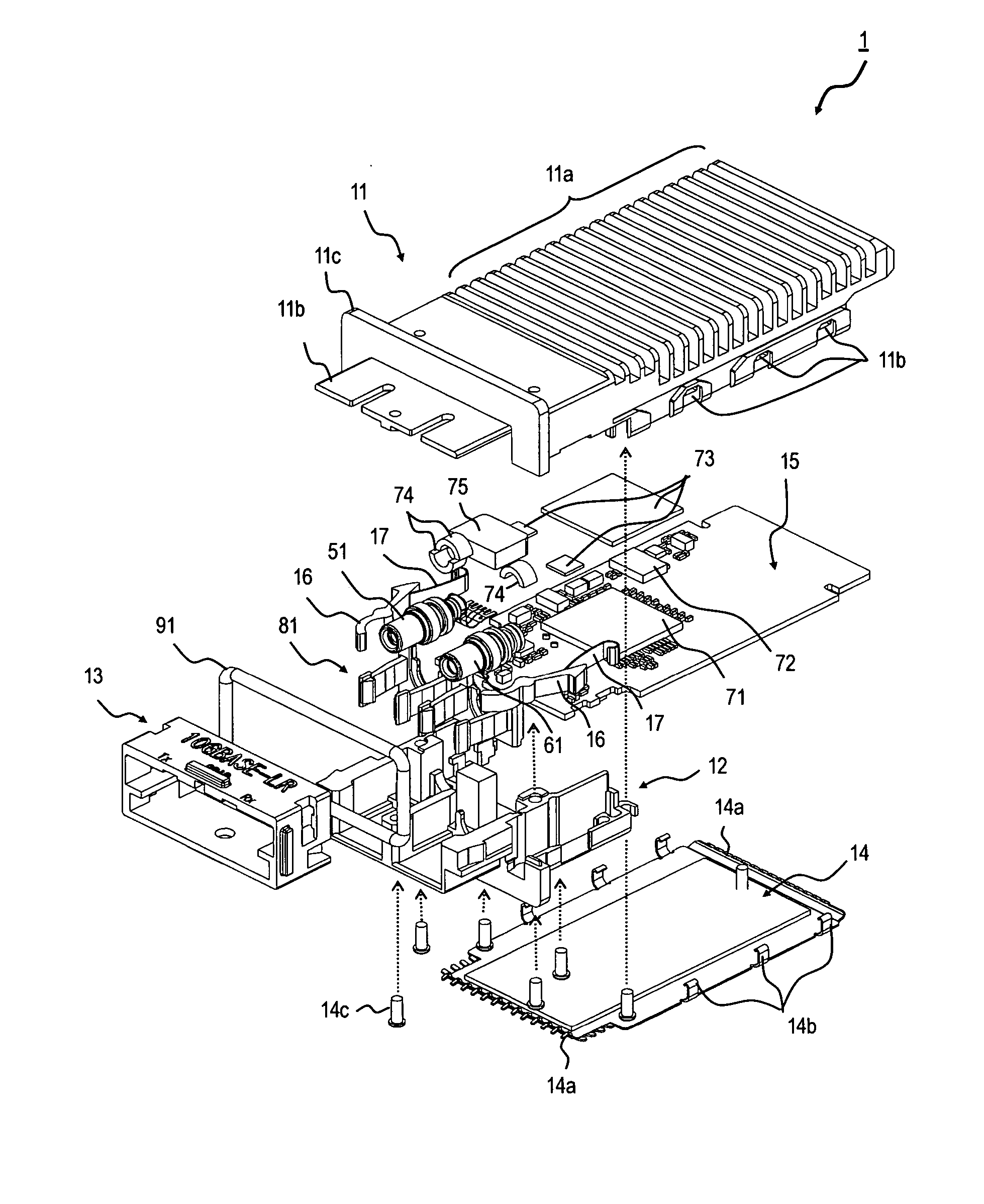
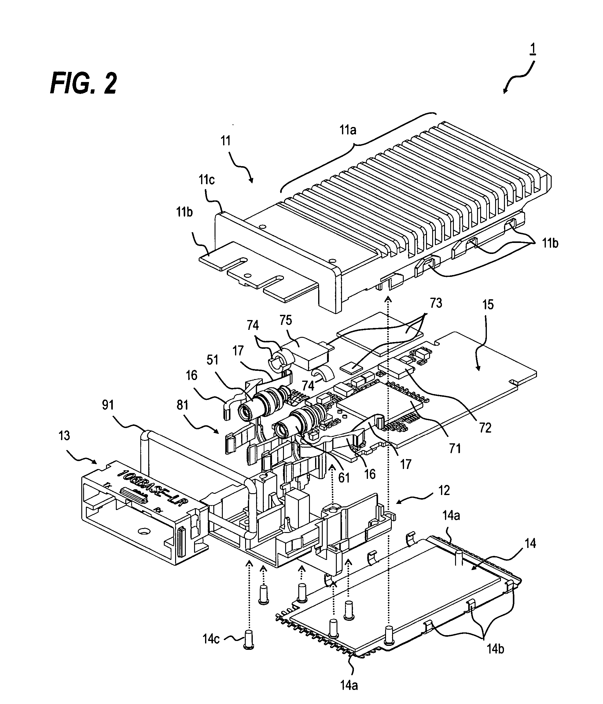
[0028] Next, as referring to accompanying drawings, structures, manufacturing methods and functions of the present optical transceiver will be described.
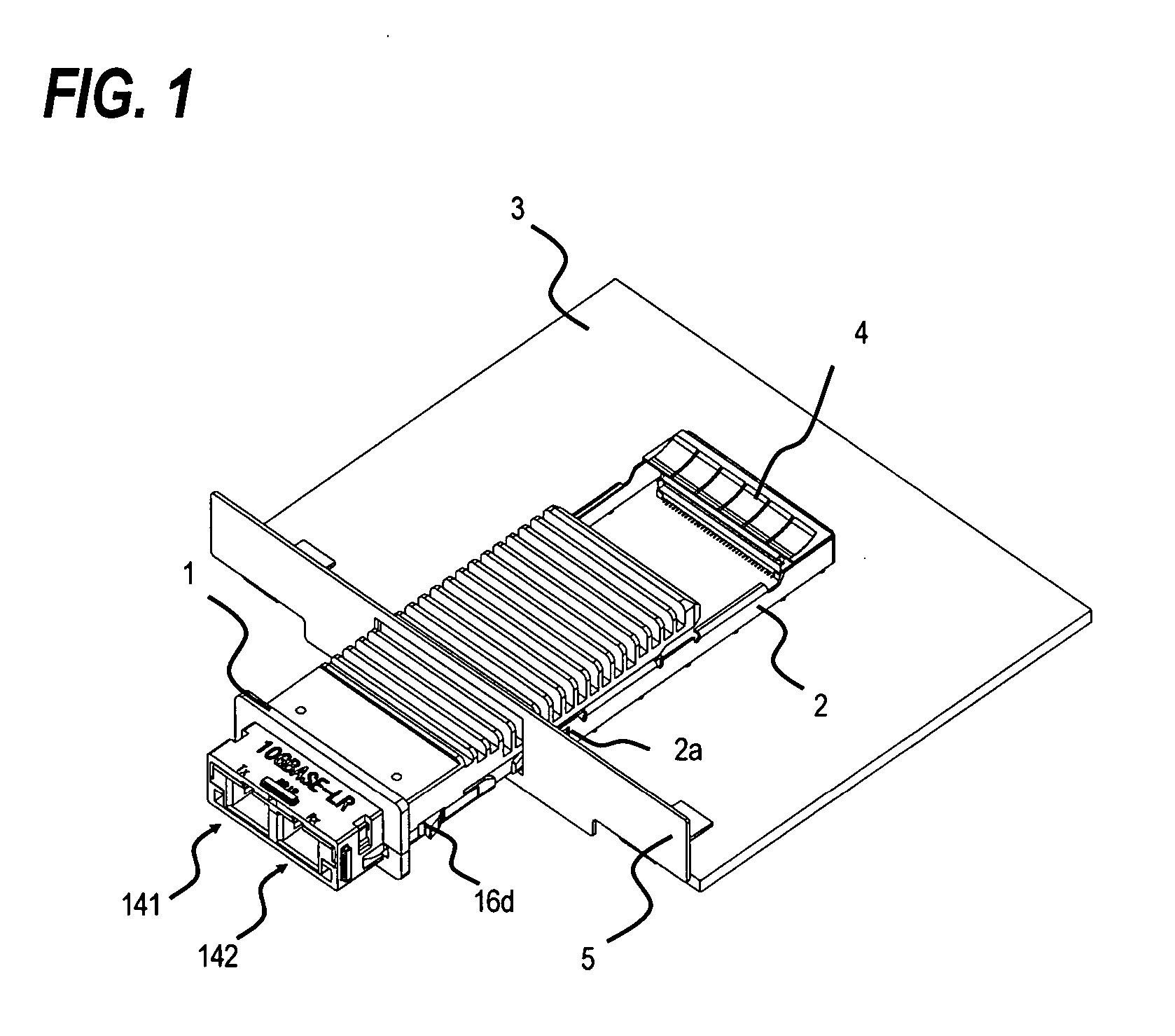
[0029]FIG. 1 shows an optical transceiver 1 of the present invention installed on the host substrate 3. The host substrate 3 provides a face panel 3 with an opening into which the transceiver passes. The rail 2 on the host substrate 3 connects to this opening of the face panel 5 such that the transceiver 1 is inserted into the rail 2 by passing through the opening of the face panel 5. The rear of the rail 2 installs a connector 4 that electrically connects the transceiver to the host substrate 3.
[0030] Both the side of the rail 2 and the side of the transceiver provide latch mechanisms, 2a and 16d, respectively. The latch mechanism is that the transceiver 1 can not released from the rail 2 until some action is operated therebetween after the transceiver is inserted thereinto and an electrical plug formed in the rear of the transce...
PUM
 Abstract
Description
Claims
Application Information