
Dust reducing apparatus for vehicle

a technology of dust reducing apparatus and vehicle, which is applied in the direction of chairs, windows, transportation and packaging, etc., can solve the problems of inability to easily eliminate pollen attached to baggage or clothes brought into the passenger compartment, inability to capture pollen on the floor of conventional vehicular air conditioning system, and inability to eliminate pollen in the passenger compartment in a short tim

Inactive Publication Date: 2005-12-22
TOYOTA JIDOSHA KK
View PDF5 Cites 26 Cited by
  • Summary
  • Abstract
  • Description
  • Claims
  • Application Information

AI Technical Summary

Benefits of technology

[0010] While taking the above facts into account, the present invention provides a dust reducing apparatus capable of reliably eliminating dust and the like such as pollen existing in a passenger compartment within a short time.
[0011] A first aspect of the invention is to provide a dust reducing apparatus for reducing an amount of dust in a passenger compartment of a vehicle, the apparatus including: an air cleaning apparatus which includes a filter, and suctions air in the passenger compartment from a lower position thereof and causes the air to pass through the filter, thereby eliminating dust in the air.
[0012] According to the dust reducing apparatus of the first aspect, after a passenger gets into the vehicle for example, the air cleaning apparatus is operated automatically or by means of manual operation of a switch. The air cleaning apparatus suctions air in the passenger compartment and causes the air to pass through the filter, and clean air from which dust such as pollen has been eliminated is discharged into the passenger compartment. That is, dust is captured by the filter. As a result, the amount of dust in the passenger compartment is reduced.

Problems solved by technology

In the automobile to which the conventional vehicular air conditioning system is applied, however, even if the inside air introducing port includes the pollen eliminating filter, pollen in the passenger compartment can not be eliminated within a short time.
Further, although most of pollen naturally drop on a floor of the passenger compartment, the conventional vehicular air conditioning system can not capture the pollen on the floor.
Pollen attached to a baggage or clothes brought into the passenger compartment can not easily be eliminated by the air circulated by the air conditioning system.

Method used


Image

  • Dust reducing apparatus for vehicle
  • Dust reducing apparatus for vehicle
  • Dust reducing apparatus for vehicle

Examples


first embodiment

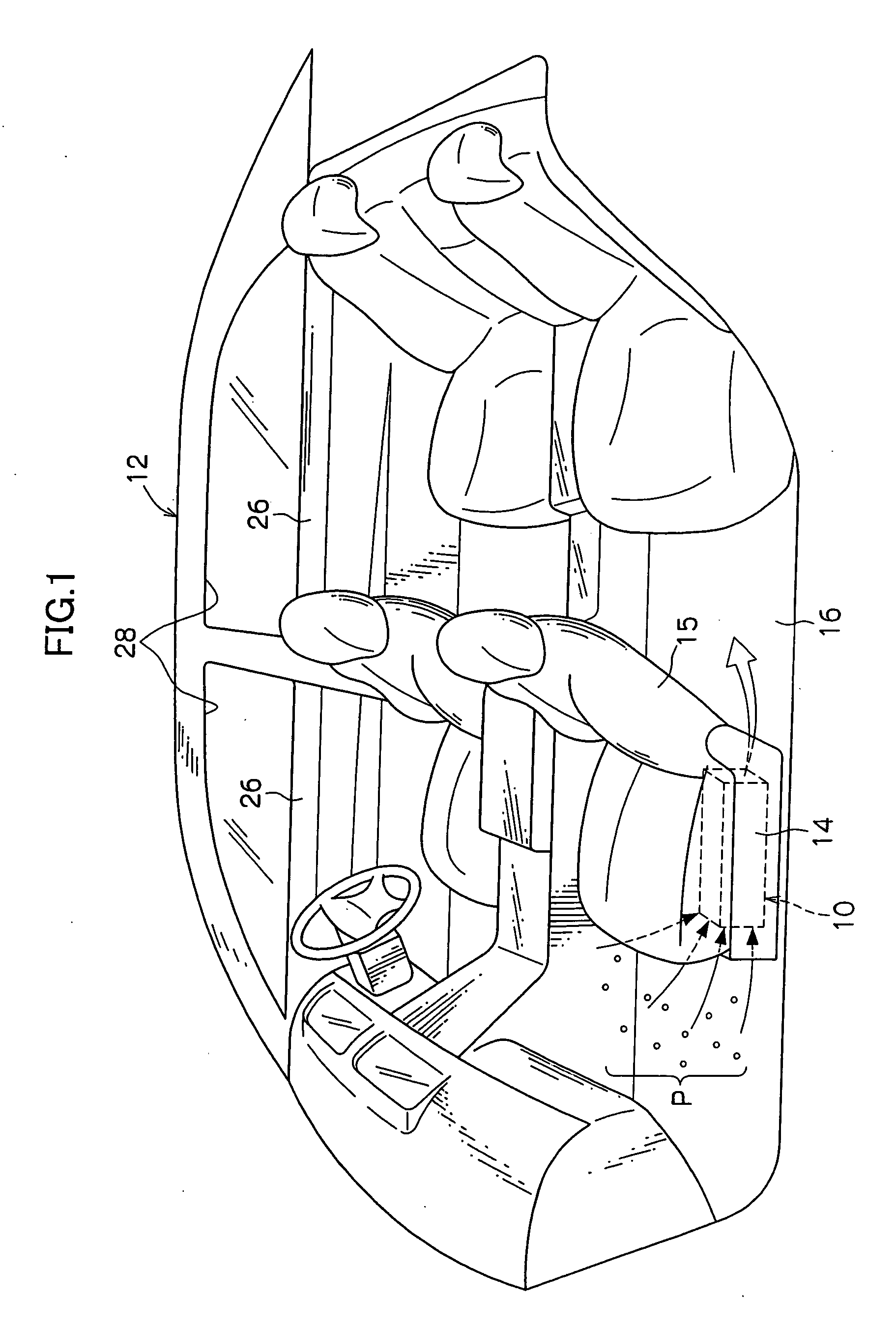
[0049] An example in which a pollen eliminating apparatus 10 as a dust reducing apparatus of a first embodiment of the present invention is applied to an automobile 12 as a vehicle will be described based on FIGS. 1 and 2.

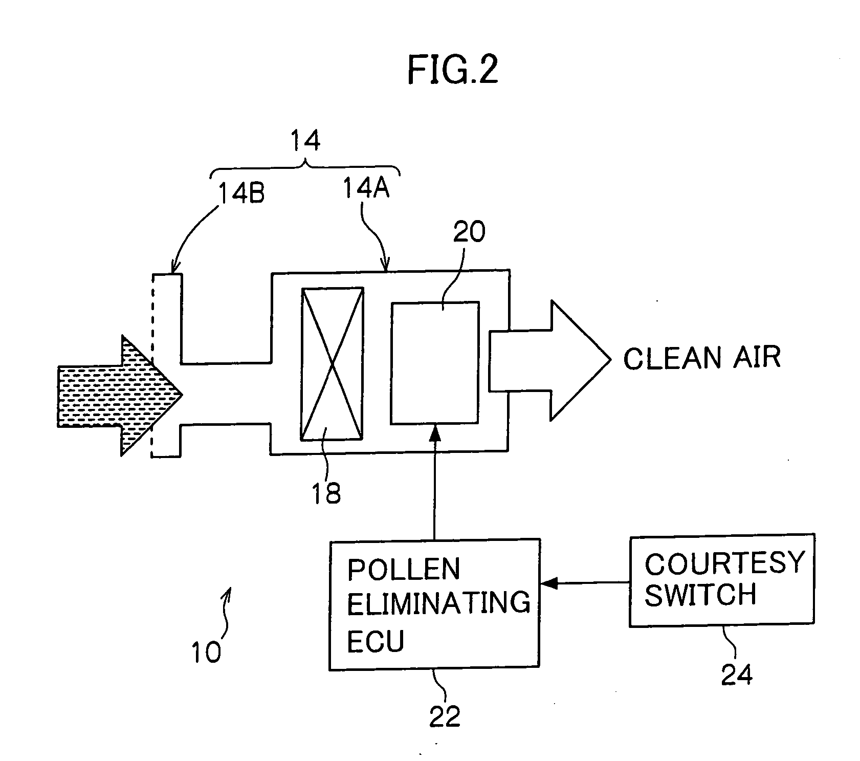
[0050]FIG. 1 is a perspective view showing an inside of a passenger compartment of the automobile 12. As shown in FIG. 1, an air cleaning apparatus 14 is provided in the passenger compartment of the automobile 12. In the first embodiment, the air cleaning apparatus 14 is disposed on a floor 16 under a passenger seat 15 (seat next to the driver). As shown in FIG. 2, the air cleaning apparatus 14 includes a body 14A and a suction unit 14B which are in communication with each other. A pollen eliminating filter 18 and a fan 20 are disposed in the body 14A.

[0051] The air cleaning apparatus 14 is designed such that, when the fan 20 is operated, the air cleaning apparatus 14 suctions air from the suction unit 14B, and discharges this air from the body 14A through a poll...

second embodiment

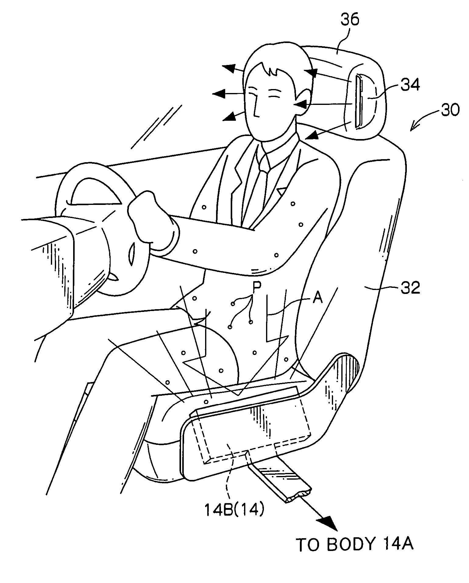
[0062] A pollen eliminating apparatus 30 as a dust reducing apparatus of a second embodiment of the invention will be described based on FIG. 3.

[0063] As shown in FIG. 3, a pollen eliminating apparatus 30 includes the air cleaning apparatus 14. The suction unit 14B of the air cleaning apparatus 14 is disposed on one side of a driver's seat 32 so that the suction unit 14B suctions air from relatively upper position of the body of the air cleaning apparatus 14. The body 14A (not shown) is disposed below the passenger seat 15 as similar as the first embodiment. In the second embodiment, in addition to the suction unit 14B shown in FIG. 3, the air cleaning apparatus 14 also includes another suction unit 14B (not shown) which is suitable for suctioning pollen P on the floor 16 or pollen P caught up by the wind from the floor 16.

[0064] The pollen eliminating apparatus 30 includes blowers 34 provided at upper portions in the passenger compartment of the automobile 12. In the second embod...

third embodiment

[0073] A pollen eliminating apparatus 40 as a dust reducing apparatus according to a third embodiment of the invention will be described based on FIGS. 4 to 6.

[0074] As shown in FIG. 4A, the pollen eliminating apparatus 40 includes a minus ion generator 42 as an ion generator. The minus ion generator 42 is configured to eject minus ions (electrons) into the passenger compartment when it is operated, and negatively charges pollen P floating or scattered in the air in the passenger compartment. As shown in FIG. 5, the minus ion generator 42 (especially a minus ion ejecting portion) is disposed at a central portion of a front end of an inner surface of a roof 48.

[0075] The pollen eliminating apparatus 40 further includes a charging unit 46 capable of positively charging a sunshade 44 as a dust attracting member. The charging unit 46 selectively generates a charged state in which the sunshade 44 is positively charged, and a de-electrified state in which this charged state is released....


PUM


Abstract

A pollen eliminating apparatus 10 which is a dust reducing apparatus applied to an automobile 12 includes an air cleaning apparatus 14 which is provided independently from an air conditioning system of the vehicle and which is disposed on a floor 16 in a passenger compartment for suctioning air from a lower position of the passenger compartment. The air cleaning apparatus allows the suctioned air to pass through a filter, thereby capturing pollen P in the air. With this structure, it is possible to provide a dust reducing apparatus capable of reliably eliminating dust such as pollen existing in the passenger compartment within a short time.

Description

CROSS-REFERENCE TO RELATED APPLICATION [0001] This application claims priority under 35 U.S.C. 119 from Japanese Patent Application No. 2004-182226, the disclosure of which is incorporated by reference herein. BACKGROUND OF THE INVENTION [0002] 1. Field of the Invention [0003] The present invention relates to a dust reducing apparatus for reducing an amount of dust and the like such as pollen in a passenger compartment of a vehicle such as an automobile. [0004] 2. Description of the Related Art [0005] In recent years, patients suffering from pollinosis are increasing. As measures against the pollinosis, a vehicular air conditioning system for preventing pollen from entering into a passenger compartment of an automobile has been devised (see Japanese Patent Application Laid-open (JP-A) No. 8-310230 for example). In such a vehicular air conditioning system, a downstream portion of an outside air introducing port in a duct of the air conditioning system is divided into a first and seco...

Claims


Application Information

Patent Timeline
Patent Type & Authority Applications(United States)
IPC IPC(8): B60H1/24B60H1/34B60H3/00B60H3/06B60J1/20
CPCB60H1/247B60H3/00B60J1/2011B60H3/06B60H3/0071B60N2/56
Inventor TAKEDA, HIRONOBUKATO, YASUSHI
Owner TOYOTA JIDOSHA KK
Learn More