Method of variable position strap mounting for RFID transponder

a technology of rfid transponders and straps, which is applied in the direction of paper/cardboard containers, mechanical actuation of burglar alarms, instruments, etc., can solve the problems of reducing the accuracy required for chip placement during manufacture, increasing complexity, thickness and inflexibility of rfid devices, and being larger than many desired rfid device form factors

Active Publication Date: 2005-12-22
AVERY DENNISON CORP
View PDF28 Cites 43 Cited by
  • Summary
  • Abstract
  • Description
  • Claims
  • Application Information

AI Technical Summary

Problems solved by technology

Structures for these purposes can add complexity, thickness and inflexibility to an RFID device.
While the length of this type of antenna may be short for the operating frequency of an RF tag, it may still be larger than many desired RFID device form factors.
The larger area reduces the accuracy required for placement of chips during manufacture while still providing effective electrical connection.
Chip placement and mounting are serious limitations for high-speed manufacture.
Metallic objects in the operating environment, including other RFID transponders, can shift the resonant frequency of an RFID transponder thereby decreasing its effective range.
Moisture content and / or humidity in the operating environment have further been known to adversely affect RFID transponder performance.
While the effects of these materials and operating environment conditions may be avoided by removing them from the RFID operating environment, it is often not practical to do so.
For example, when using an RFID transponder to track a package containing a metallic object, it may not be practical to remove the metallic object from the package to facilitate reading the RFID transponder.
However, this method is not well suited for high-speed, low cost implementation of RFID transponders because it may require adding or removing elements of an antenna and manipulation of more than one component.
In comparison with the production of RFID devices with antennas and electronics that have been predesigned for improved performance, however, this method of producing RFID transponders on objects suffers the shortcoming that the coupling of the electronics to the antenna may yield sub-optimal, inferior performance.

Method used


Image

  • Method of variable position strap mounting for RFID transponder
  • Method of variable position strap mounting for RFID transponder
  • Method of variable position strap mounting for RFID transponder

Examples


Embodiment Construction

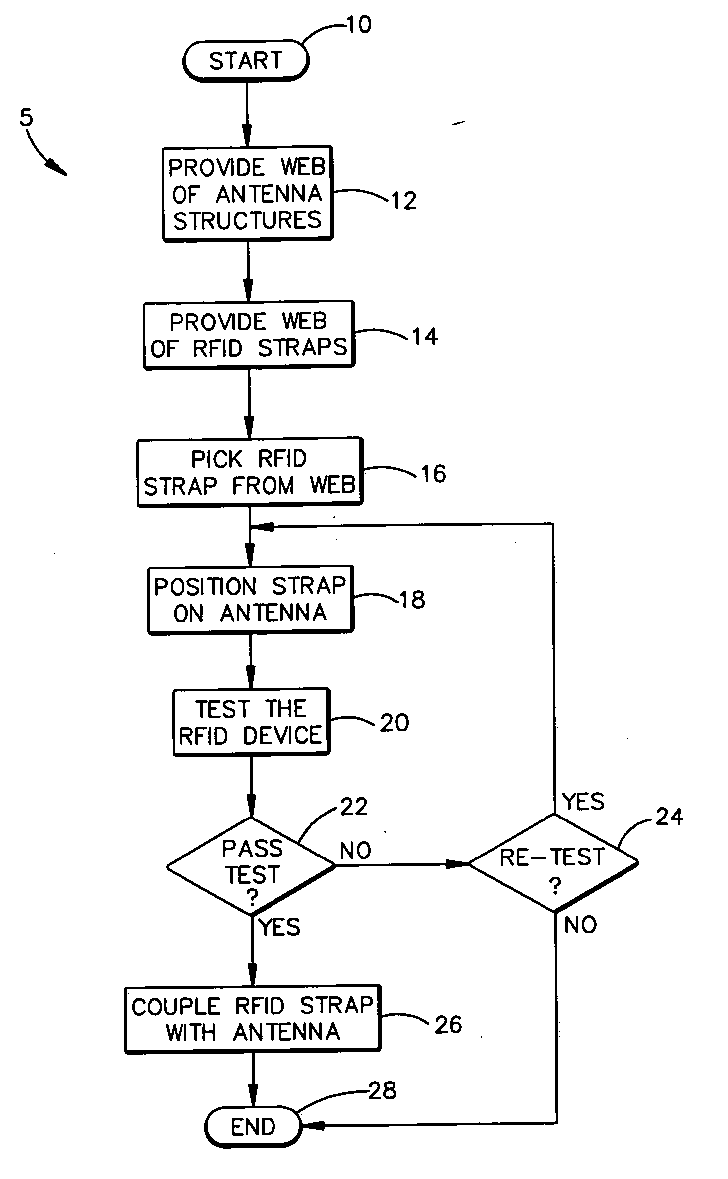
[0031] A method of coupling an RFID chip to an antenna includes the steps of, iteratively until a test criterion is met, positioning an RFID chip relative to an antenna and testing the RFID chip and antenna. Once the test criterion is met, the RFID chip is coupled with the antenna. A method of coupling an RFID chip to one of a plurality of various antennas is also provided. A method of coupling an RFID chip to an antenna on an object is also provided.

[0032] In FIG. 1, a flowchart depicting a method 5 of variable attachment of an RFID strap to an antenna is shown. The method 5 begins with providing a web of antenna structures in process step 12. The web of antenna structures may be a web of antenna structures as disclosed in commonly-assigned U.S. patent application Ser. No. 10 / 805,938. In process step 14, a web of RFID straps is provided. An individual RFID strap is picked, separated, or severed from the web of RFID straps and positioned on an antenna structure in process steps 16 ...


PUM

PropertyMeasurementUnit
thicknessaaaaaaaaaa
attach angleaaaaaaaaaa
resonant frequenciesaaaaaaaaaa

Abstract

A method of coupling an RFID chip to an antenna includes the steps of, iteratively until a test criterion is met, positioning an RFID chip relative to an antenna and testing the RFID chip and antenna. Once the test criterion is met, the RFID chip is coupled with the antenna. A method of coupling an RFID chip to one of a plurality of various antennas is also provided. A method of coupling an RFID chip to an antenna on an object is also provided.

Description

BACKGROUND OF THE INVENTION [0001] 1. Field of the Invention [0002] The present invention relates generally to the assembly of electronic devices. More particularly, the present invention relates to the assembly of radio frequency identification (RFID) straps interposers and / or tags. [0003] 2. Description of the Related Art [0004] Radio frequency identification (RFID) tags and labels (collectively referred to herein as “devices”) are widely used to associate an object with an identification code. RFID devices generally have a combination of antennas and analog and / or digital electronics, which may include for example communications electronics, data memory, and control logic. Furthermore the RFID devices include structures to support and protect the antennas and electronics, and to mount or attach them to objects. For example, RFID tags are used in conjunction with security-locks in cars, for access control to buildings, and for tracking inventory and parcels. Some examples of RFID ...

Claims


Application Information

Patent Timeline
Patent Type & Authority Applications(United States)
IPC IPC(8): G06K19/077G08B13/14
CPCG06K7/0095G06K19/0726Y10T29/49124Y10T156/1075Y10T156/10G06K19/07749G06K19/07G06K19/077
Inventor FORSTER, IAN J.
Owner AVERY DENNISON CORP
Why Eureka
Try Eureka