Lacrosse handle

a handle and lacrosse technology, applied in the field of lacrosse handles, can solve the problems of reducing dents and cracks, and achieve the effects of improving the handle, reducing dents and cracks, and increasing strength and durability

Inactive Publication Date: 2005-12-22
WARRIOR LACROSSE
View PDF11 Cites 13 Cited by
  • Summary
  • Abstract
  • Description
  • Claims
  • Application Information

AI Technical Summary

Benefits of technology

[0007] It is therefore one advantage of the present invention to provide an improved handle for a lacrosse head that provides tactile stimuli or feedback such that a player can sense the orientation of a lacrosse head attached to the handle without the need for visual inspection.
[0008] It is another advantage of the present invention to provide a lacrosse handle having increased strength and durability. In other words, additional material (metal) added to the interior of the sidewall intersections results in a decrease in dents and cracks where they most frequently occur.
[0009] It is a related advantage of the present invention to provide a lacrosse handle for a lacrosse head having increased strength and durability that does not require a significant increase in the weight of the handle.
[0010] It is yet another advantage of the present invention to provide a handle for a lacrosse head that yields improved playability and handling.
[0011] It is still another object of the present invention to provide a lacrosse handle for attachment to a lacrosse head that has a varying or non-uniform wall thickness.
[0012] In accordance with the above and the other advantages of the present invention, a handle for a lacrosse head is provided. The handle includes a hollow metal tube having an interior surface and an exterior surface. The hollow metal tube has a first end for communicating with a throat portion of a lacrosse head and a second end opposing the first end. The exterior surface includes a plurality of sidewalls meeting at a plurality of intersections. The hollow tube has a first thickness defined between each of the plurality of intersections and the interior surface. The hollow tube has a second thickness defined between at least one of the sidewalls and the interior surface. The first thickness has a greater magnitude than the second thickness.

Problems solved by technology

In other words, additional material (metal) added to the interior of the sidewall intersections results in a decrease in dents and cracks where they most frequently occur.

Method used


Image

  • Lacrosse handle
  • Lacrosse handle

Examples


Embodiment Construction

[0018] In the following figures, the same reference numerals are used to identify the same components in the various views.

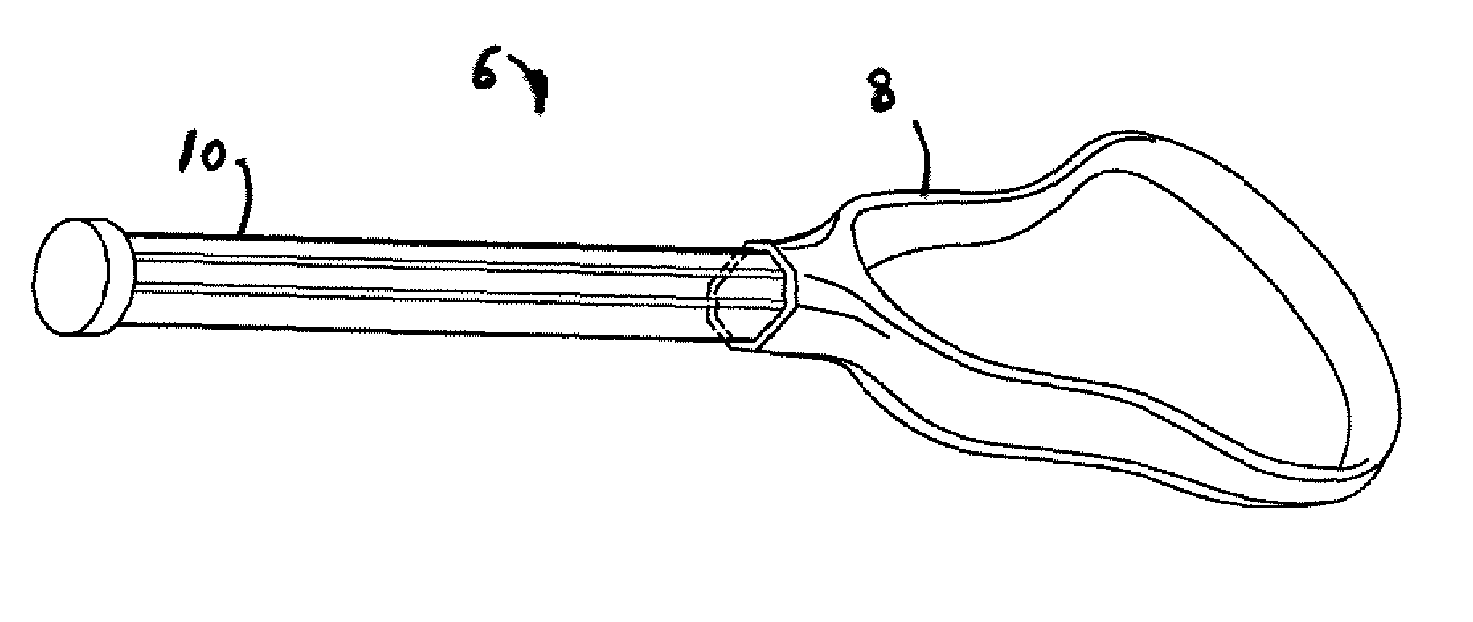
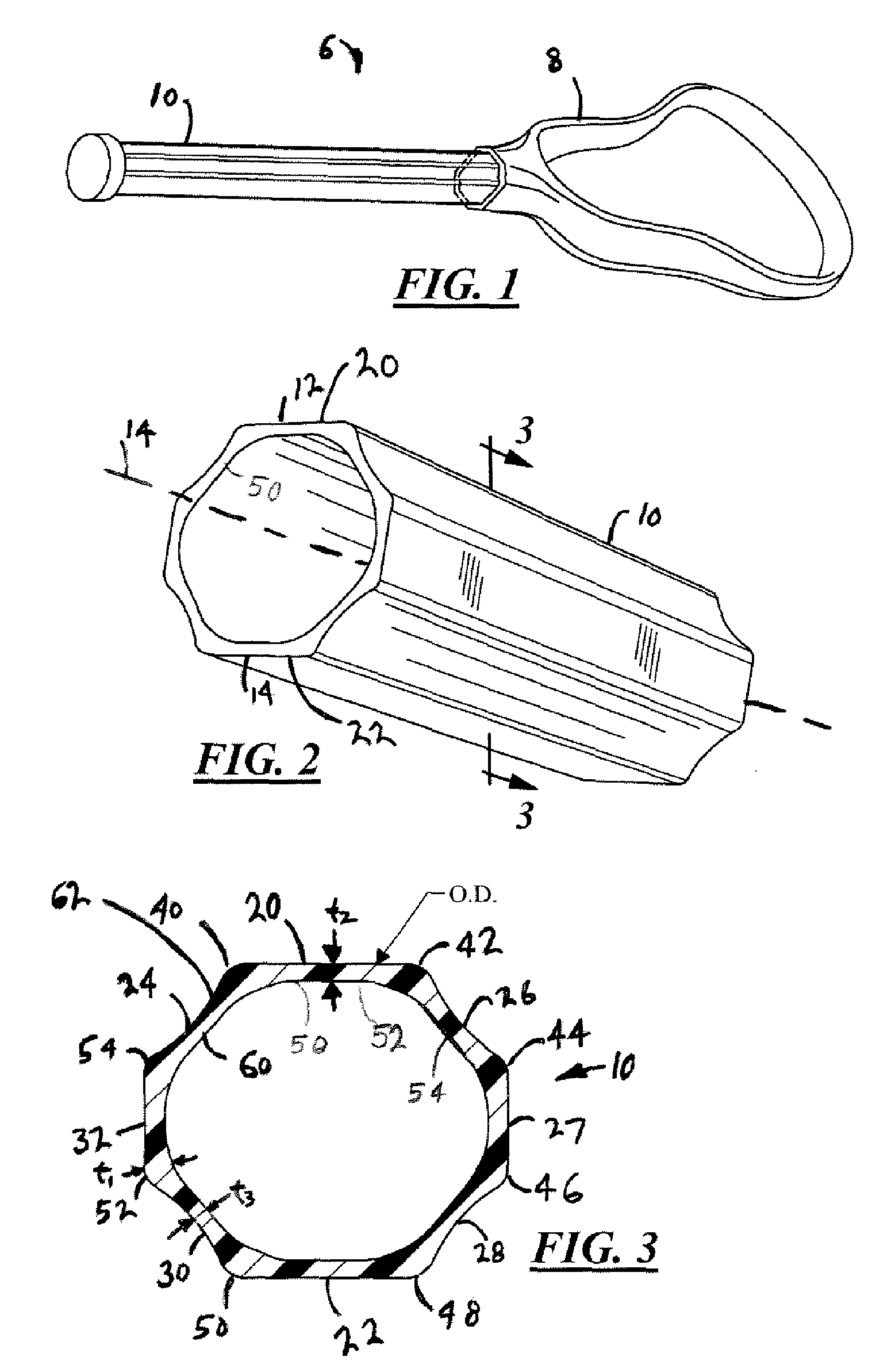
[0019] In the embodiment, illustrated in FIGS. 1 through 3, a lacrosse stick 6 having a lacrosse head 8 coupled to a lacrosse handle 10 having areas of increased wall thickness is shown. The lacrosse handle 10 is preferably an eight-sided structure that is generally symmetrically shaped on either side of a handle centerline as is well known in the art. It will be understood, however, that the lacrosse handle can take on a variety of different shapes. The lacrosse handle 10 is preferably constructed of metal, such as aluminum or titanium. However, the handle may be formed of a variety of other materials, such as a variety of alloys. The handle is preferable formed by an extrusion process, however, a variety of other suitable manufacturing processes may also be utilized. The handle 10 also is preferably constructed as a hollow metal tube with a top portion 12 and...


PUM


Abstract

A handle for a lacrosse head is provided. The handle includes a hollow metal tube having an interior surface and an exterior surface. The hollow metal tube also has a first end for communicating with a throat portion of a lacrosse head and a second end opposing the first end. The exterior surface includes a plurality of sidewalls meeting at a plurality of intersections. The intersections have cross-sectional widths of greater magnitude than the sidewalls.

Description

CROSS-REFERENCE TO RELATED APPLICATIONS [0001] The present invention claims priority from U.S. Provisional Application Ser. No. 60 / 581,488, filed Jun. 21, 2004, and entitled “Handle With Increased Strength”.TECHNICAL FIELD [0002] The present invention relates generally to a lacrosse handle for attachment to a lacrosse head. More particularly, the present invention relates to a lacrosse handle for attachment to a lacrosse head that has increased strength and resistance to breakage or damage. BACKGROUND OF THE INVENTION [0003] Original lacrosse handles were constructed of wood. These wood handles were shaped such that the lacrosse handle and the lacrosse head were a single one-piece wood structure. These wooden lacrosse handles suffered from a variety of disadvantages. Initially, these wooden handles were susceptible to damage from excess exposure to water such as through warping. Further, these prior wooden handles were heavy and somewhat cumbersome and also susceptible to breakage. ...

Claims


Application Information

Patent Timeline
Patent Type & Authority Applications(United States)
IPC IPC(8): A63B59/00A63B59/02A63B65/12
CPCA63B59/0014A63B2243/005A63B59/02A63B60/10A63B2102/14A63B60/06A63B59/20A63B60/08A63B60/00
Inventor MORROW, DAVID
Owner WARRIOR LACROSSE
Why Eureka
Try Eureka