Vascular closure device

a vascular closure and incision technology, applied in the field of vascular closure devices, can solve the problems of difficult suturing in keyhole procedures or other types of surgery, and achieve the effect of preventing blood leakag

Inactive Publication Date: 2005-12-22
BY PASS
View PDF79 Cites 1334 Cited by
  • Summary
  • Abstract
  • Description
  • Claims
  • Application Information

AI Technical Summary

Benefits of technology

[0009] An aspect of some preferred embodiments of the invention relates to safety. In a preferred embodiment of the invention, if a suitab...

Problems solved by technology

In addition, it may be difficult to perform the suturing in a key-hole proce...

Method used


Image

  • Vascular closure device
  • Vascular closure device
  • Vascular closure device

Examples


Embodiment Construction

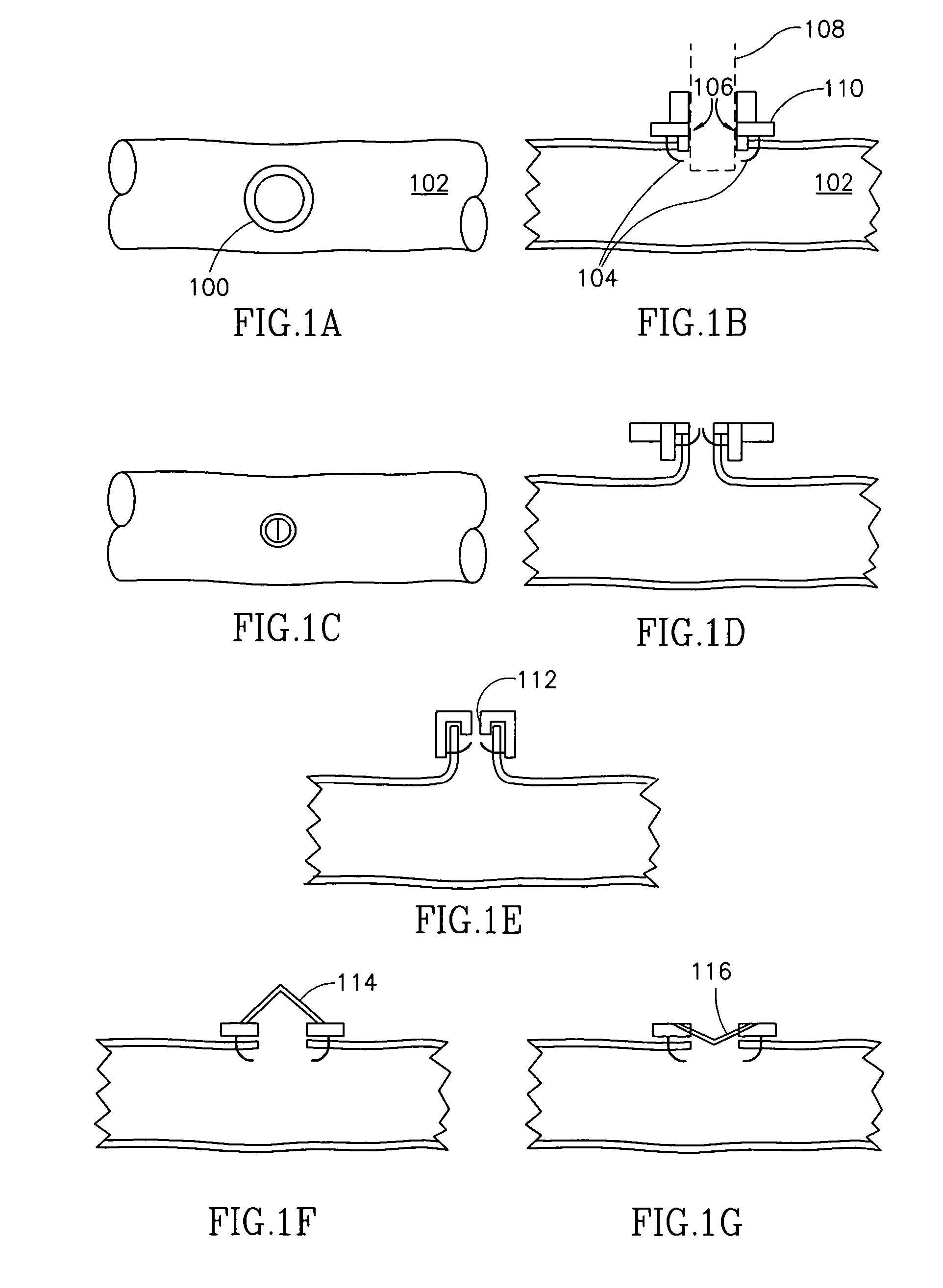
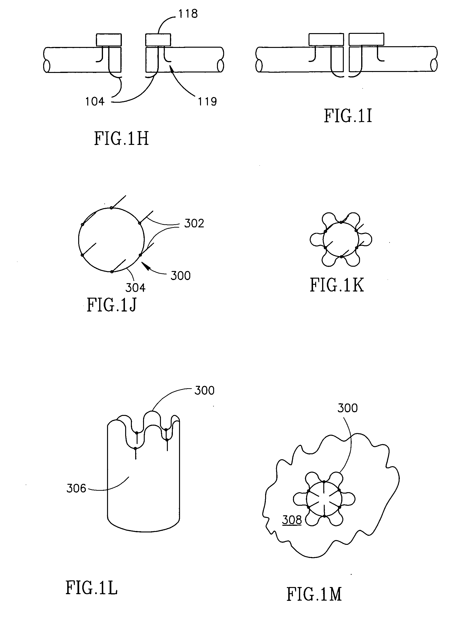
[0097]FIGS. 1A-1D illustrate a self-sealing vascular port 100 in a vessel 102, in accordance with a preferred embodiment of the invention. FIGS. 1A and 1B illustrate a top view and a side cross-sectional view (respectively) of port 100, in an open configuration and FIGS. 1C and 1D illustrate port 100 in a sealed configuration. In the following figures, some changes have been made for clarity. For example, some of the “seals” are shown partly open, the degree of eversion is exaggerated in some figures, the length of spikes is sometimes exaggerated and the amount the spikes protrude from blood vessels is sometimes exaggerated. In particular, although a 90° eversion is shown, for example in FIG. 1B, a smaller eversion or no eversion can also be accomplished. In the exemplary embodiment of FIG. 1, port 100 comprises a ring 110 having a plurality of spikes 104 to engage vessel 102. FIG. 1B shows port 100 being open and a tube 108 (dotted line) inserted in the opening of the port. In FIG....


PUM


Abstract

A method of accessing a blood vessel, comprising: forming a hole in the blood vessel; mounting a hole closure device onto the blood vessel; accessing the blood vessel through the hole, while the hole closure device is mounted on the blood vessel; and closing the hole by the hole closure device, after accessing the blood vessel through the hole.

Description

RELATED APPLICATIONS [0001] This application is a divisional of U.S. application Ser. No. 09 / 936,789 filed Sep. 17, 2001 which is a U.S. national phase of PCT application No. PCT / IL99 / 00674, filed Dec. 9, 1999, which is a continuation-in-part of PCT application No. PCT / IL99 / 000284, now U.S. application Ser. No. 09 / 701,531, PCT application No. PCT / IL99 / 00285, now U.S. application Ser. No. 09 / 701,523, and PCT application No. PCT / IL99 / 00670 all of which designate the U.S. the disclosures of which are incorporated herein by reference.FIELD OF THE INVENTION [0002] The present invention relates to vascular devices and especially to sealing vascular incisions. BACKGROUND OF THE INVENTION [0003] There are many medical procedures in which a tube is temporarily inserted into- or out of- a blood vessel. One particular example is the use of a heart-lung machine during heart surgery. A first cannula is inserted into the aorta to return blood after it was oxygenated by the heart-lung machine. One...

Claims


Application Information

Patent Timeline
IPC IPC(8): A61B17/00A61B17/08A61B17/122A61B17/128
CPCA61B17/0057A61B2017/1135A61B17/0643A61B17/0644A61B17/068A61B17/083A61B17/11A61B17/115A61B17/1227A61B17/128A61B17/32053A61B2017/00637A61B2017/00663A61B2017/00668A61B2017/00867A61B2017/0641A61B2017/1107A61B17/064
Inventor LOSHAKOVE, AMIRKILEMNIK, IDOKEREN, DVIR
Owner BY PASS
Why Eureka
Try Eureka