Duct joint layout tool

a technology of layout tool and duct joint, which is applied in the direction of distance measurement, instruments, writing aids, etc., can solve the problems of not being able to take advantage of the t-flange and not being able to work with pre-formed rectangular cross-section ducts

Inactive Publication Date: 2005-12-29
EBERLY DWAYNE K
View PDF23 Cites 7 Cited by
  • Summary
  • Abstract
  • Description
  • Claims
  • Application Information

AI Technical Summary

Benefits of technology

[0015] A portion of the main body structure is removed to form an interior structure having a straight edge oriented perpendicular to the base-edge flange. The perpendicular straight edge aids in layout and cutting of duct faces that must be cut perpendicular to the longitudinal duct axis to form a mitered duct joint.

Problems solved by technology

The limitation with this right-triangular design is that the second leg of the right triangle is always perpendicular to the flange, leaving only the hypotenuse available for non-perpendicular layout lines.
In the former method, making a layout line is a three-step process; the second method requires two steps and fails to take advantage of the T-flange for quick and accurate tool alignment with the workpiece.
These tools are designed to make layout lines and cuts on ductboard material in sheet form needed to form rectangular cross-section ducts, but they are not suited to working with pre-formed rectangular cross-section ducts.

Method used


Image

  • Duct joint layout tool
  • Duct joint layout tool
  • Duct joint layout tool

Examples


Embodiment Construction

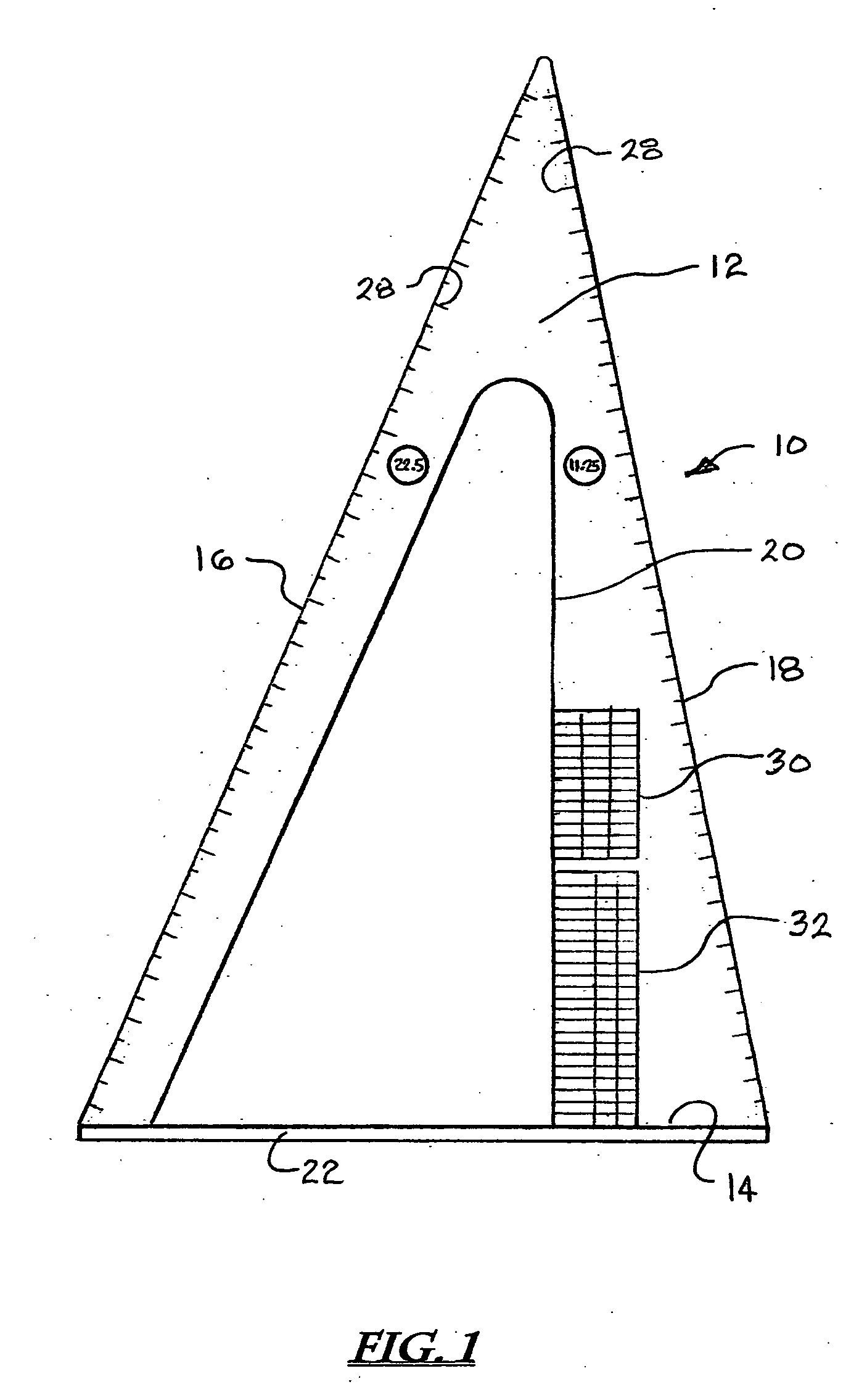
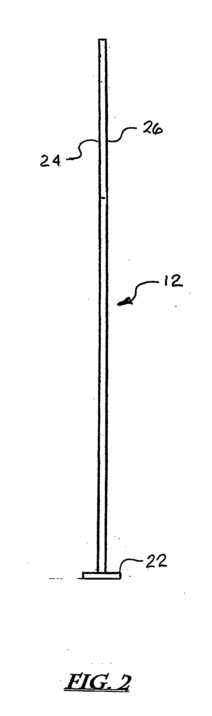
[0033] The preferred embodiment shown in FIG. 1 is a layout tool 10 consisting of a main body structure 12 having a generally triangular periphery and a substantially planar surface. The periphery of main body structure 12 is formed by base edge 14, 22.5-degree straight edge 16, and 11.25-degree straight edge 18. In the preferred embodiment, base edge 14 measures approximately 14-⅝ inches long, 22.5-degree straight edge 16 is approximately 25-⅝ inches long, and 11.25-degree straight edge is approximately 24-⅛ inches long. A portion of main body structure 12 is removed to form an interior opening that includes 90-degree straight edge 20. The layout tool 10 has a first planer surface 24 facing in one direction and a second planar surface 26 facing in the opposite direction, said surfaces being parallel and separated by a short distance ranging from about ⅛ inch to ¼ inch. Though the invention may be made of any suitably rigid material, such as steel, aluminum, or plastic, the preferre...


PUM

PropertyMeasurementUnit
included angleaaaaaaaaaa
miter-cut angleaaaaaaaaaa

Abstract

The invention is a layout tool and a means for using the tool to fabricate multi-segment elbows and offset joints from rectangular cross-section fibrous air ductboard material. The tool has a triangular main body having at least one structural feature that defines a plane. At least one flange is connected to the main body, is oriented substantially perpendicular to the main body plane, and forms the first side of the triangle. The main body includes a first outer straight edge extending at an angle of 67.50 degrees from the flange forming the second side of the triangle. A second outer straight edge extending at an angle of 78.75 degrees from the flange forms the third side of the triangle. An inner structure of the main body forms a straight edge perpendicular to the plane of the flange. The outer angled and interior straight edges enable 22.5- and 45-degree miter joints to be easily marked and cut in pre-formed fibrous air duct. Markings on the main body indicate required distances between cuts to accomplish desired offset rises.

Description

BACKGROUND OF THE INVENTION [0001] 1. Field of the Invention [0002] This invention relates generally to the field of measuring and marking tools having a generally triangular configuration and a flange, perpendicular to one side, projecting above and below the upper and lower surfaces of the triangle, and upon which linear measurement markings are provided on the surfaces of the triangle along the respective edge portions. In particular, this invention relates to tools having a scalene triangular configuration in which the angular orientation of the sides relative to the flange are common angles used in mitered construction and markings on a surface of the triangle providing commonly used mitered air duct joint fabrication measurements. [0003] The use of fibrous ductboard material for heating and air conditioning ducts is well known. Such ductboard typically includes a layer of fiberglass attached to a composite outer covering. The outer covering is typically made up of a layer Kraf...

Claims


Application Information

Patent Timeline
Patent Type & Authority Applications(United States)
IPC IPC(8): B23P17/00
CPCB43L7/033G01B3/04Y10T29/49428Y10T29/49813Y10T29/49996Y10T29/49995
Inventor EBERLY, DWAYNE K.
Owner EBERLY DWAYNE K
Why Eureka
Try Eureka