
Angular adjustment apparatus for a miter saw

a technology of miter saw and adjustment apparatus, which is applied in the field of power tools, can solve the problems of not being able to operate over the entire range of miter cut angles, not allowing for rapid or macro adjustment of the miter cut angle over a range, and being relatively complex, so as to achieve more precise adjustment of the miter cut angle of the saw. , the effect of reducing the rotational speed of the pinion gear

Active Publication Date: 2005-12-29
ROBERT BOSCH GMBH +1
View PDF20 Cites 35 Cited by
  • Summary
  • Abstract
  • Description
  • Claims
  • Application Information

AI Technical Summary

Benefits of technology

[0005] The preferred embodiments of present invention relate to a miter saw having a base and rotating turntable mounted thereon, and a miter cut angle adjustment apparatus for providing large scale rotational movement as well as fine or incremental rotational movement of the turntable with respect to the base over the entire range of miter cut angles. The turntable includes an outwardly extending handle portion for rotating the turntable, which can be moved to set the miter saw at various angles over a specified range. The preferred embodiments enable both large scale and fine rotational movement of the turntable using adjustment mechanisms that are easily accessible and operable at or very near the handle portion at the front of the saw.
[0007] In an alternative preferred embodiment, a gearing system, such as a planetary gear set is provided to reduce the rotational speed of the pinion gear relative to the turning wheel to provide more precise adjustment of the miter cut angle of the saw.

Problems solved by technology

However, due to the interaction between the lever and the detent, many of these prior art arrangements do not allow for rapid or macro adjustment of the miter cut angle over a range of angles in combination with a fine adjustment, or for fine adjustment that is near one of the pre-selected detent positions.
However, the range of fine adjustment is not capable of operating over the entire range of miter cut angles, but instead is limited to specific regions within the entire range that are centered about the detents.
While miter saws have been developed which provide for rapid large scale rotation of the turntable relative to the base and also provide some limited fine adjustment relative to the pre-selected angular settings, all known examples of such saws fail to provide rapid large scale rotation of the turntable and fine adjustment over the entire range of miter cut angles, and are relatively complex and are not easily manipulated by a user.

Method used


Image

  • Angular adjustment apparatus for a miter saw
  • Angular adjustment apparatus for a miter saw
  • Angular adjustment apparatus for a miter saw

Examples


Embodiment Construction

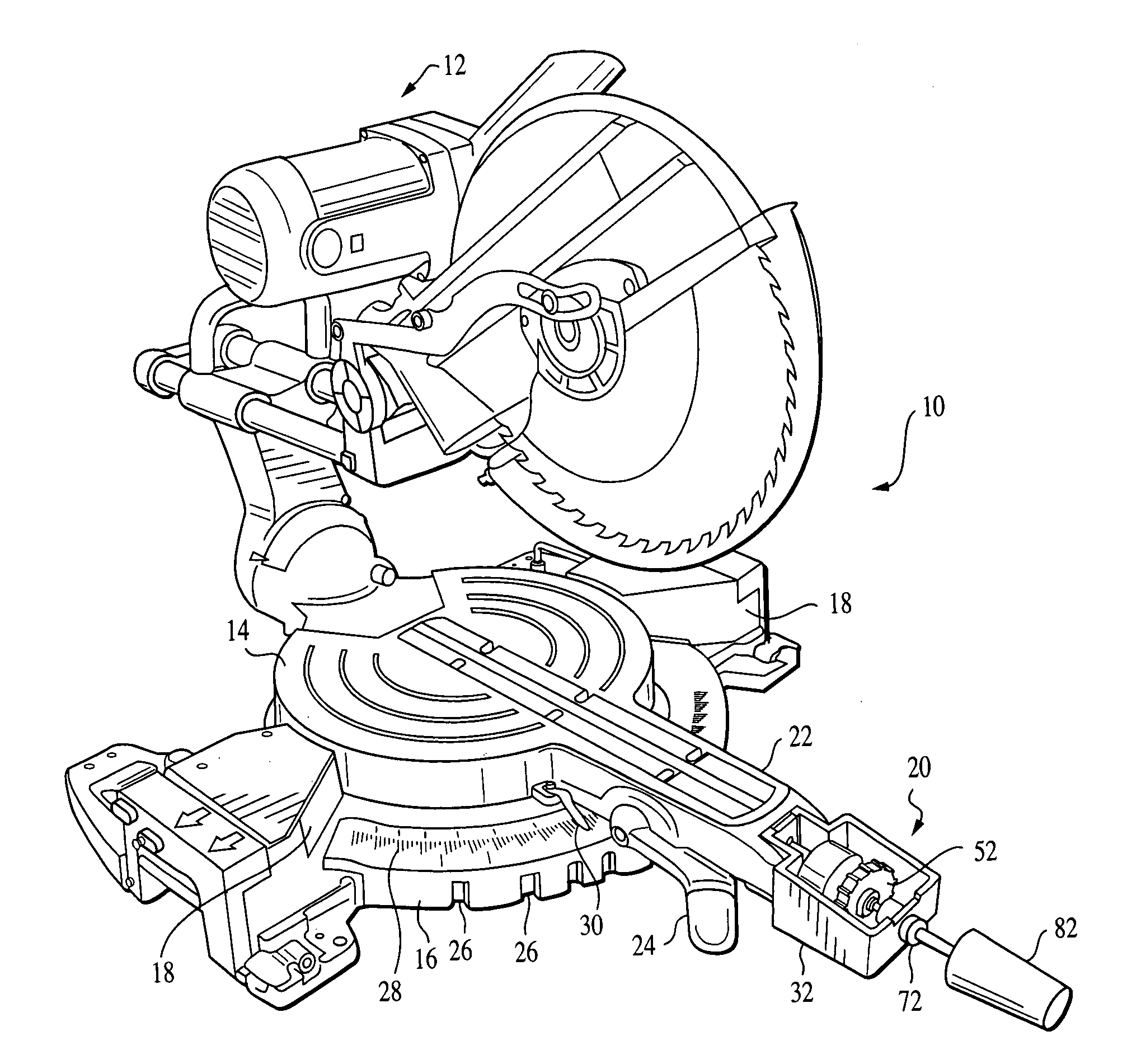
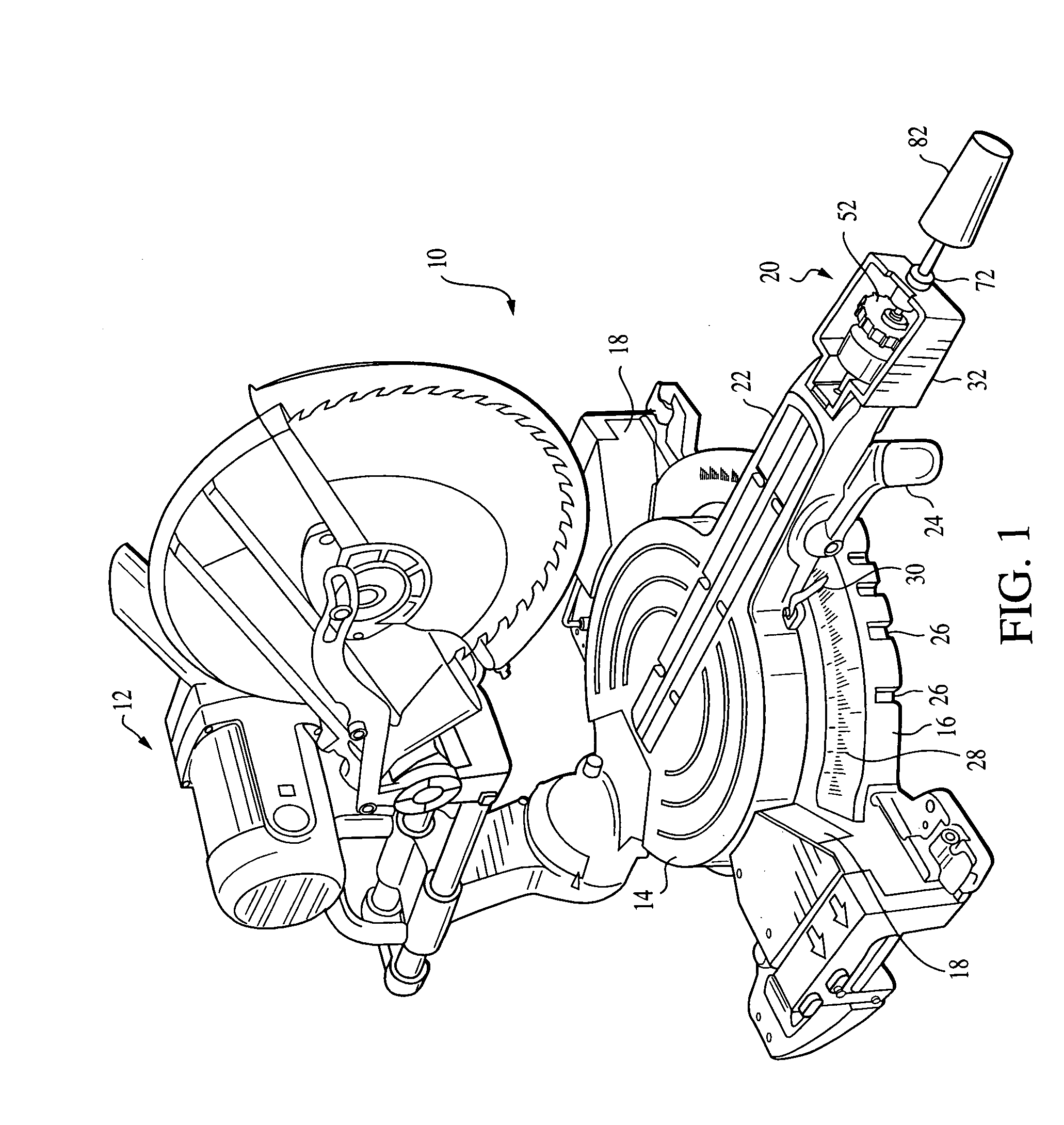
[0015] Broadly stated, the present invention is directed to an angular adjustment apparatus for a cutting tool of the type which has a base and a turntable mounted to the base and being rotatable around a central axis, wherein the turntable has an outwardly extending handle portion for rotating the turntable relative to the base. The present invention is directed to an apparatus for use in connection with precision cutting of a work piece, and provides fine or incremental adjustment of the miter cut angle of the saw.

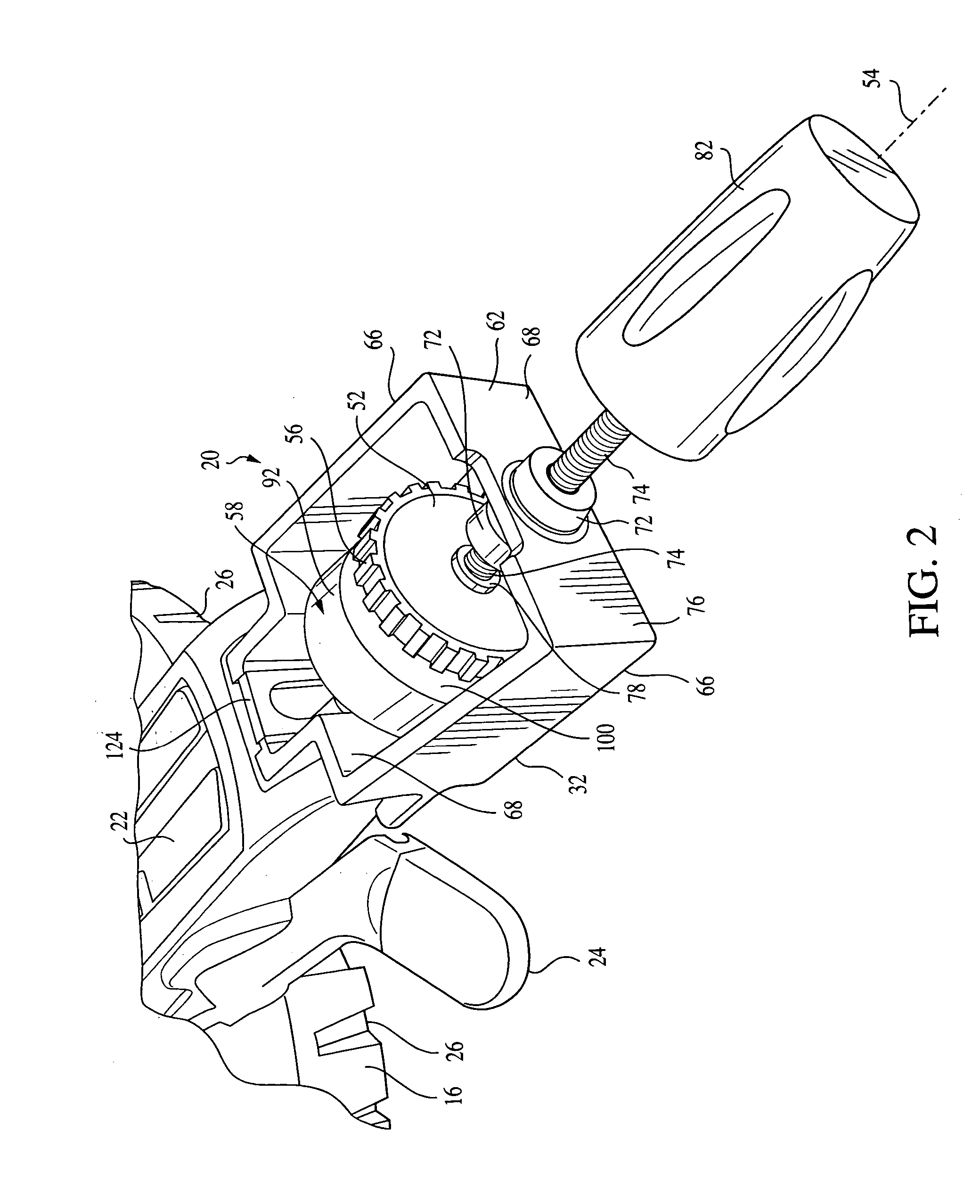
[0016] At least a portion of the angular adjustment apparatus is preferably configured to be mounted to the outwardly extending handle portion of the cutting tool so that the angular adjustment apparatus can engage the base and provide fine adjustment of the miter cut angle. The angular adjustment apparatus embodying the present invention has an arcuate rack gear positioned on the base that has a generally constant radius relative to the center axis, and an elongated ad...


PUM

PropertyMeasurementUnit
cut angleaaaaaaaaaa
cut anglesaaaaaaaaaa

Abstract

An angular adjustment apparatus for a miter saw having a base and a turntable mounted to the base and rotatable around a generally centrally located axis, the turntable having a handle portion for rotating the turntable relative to the base. The apparatus includes an arcuate rack gear positioned on the base, and an elongated adjustment mechanism associated with the handle portion. The adjustment mechanism includes a pinion gear configured to engage the rack gear when brought into contact therewith, and a control wheel operatively connected to the pinion gear. The control wheel is rotatable around an axis concentric with the pinion gear and moveable along the concentric axis to cause the pinion gear to selectively engage and disengage the rack gear, wherein rotation of the control wheel while the pinion gear is engaged with the rack gear causes the turntable to rotate relative to the base.

Description

FIELD OF THE INVENTION [0001] The present invention relates generally to power tools, and more particularly to power miter saws. BACKGROUND OF THE INVENTION [0002] Conventional miter saws often provide an arrangement where the miter cut angle can be set at a number of predetermined positions. Typically, conventional miter saws include a stationary base to which a rotatable turntable is mounted, the base providing a plurality of detents that are configured to engage a lever attached to the turntable. The turntable due to the interaction of the lever and the detent on the base, may be set to pre-selected miter cut positions. By way of example, such an arrangement may provide detents at left and right 45 and 22.5-degree locations relative to a center detent that is perpendicular to a stationary fence that is formed or mounted to the base. In addition, some miter saws also provide for adjusting the miter cut position to a location other than the predetermined detent positions. However, ...

Claims


Application Information

Patent Timeline
Patent Type & Authority Applications(United States)
IPC IPC(8): B23D45/02B23D47/02
CPCB23D45/048B27B5/29B23D47/025Y10T83/7697Y10T83/7705Y10T83/7726Y10T83/7788Y10T83/8773
Inventor TALESKY, MARK S.HIRSCHBURGER, WOLFGANG
Owner ROBERT BOSCH GMBH
Features
  • Generate Ideas
  • Intellectual Property
  • Life Sciences
  • Materials
  • Tech Scout
  • Unparalleled Data Quality
  • Higher Quality Content
  • 60% Fewer Hallucinations
Learn More