Method and system for predicting performance of a drilling system for a given formation

US20050284661A1Inactive Publication Date: 2005-12-29HALLIBURTON ENERGY SERVICES INC

Image

  • Method and system for predicting performance of a drilling system for a given formation
  • Method and system for predicting performance of a drilling system for a given formation
  • Method and system for predicting performance of a drilling system for a given formation

Examples


Embodiment Construction

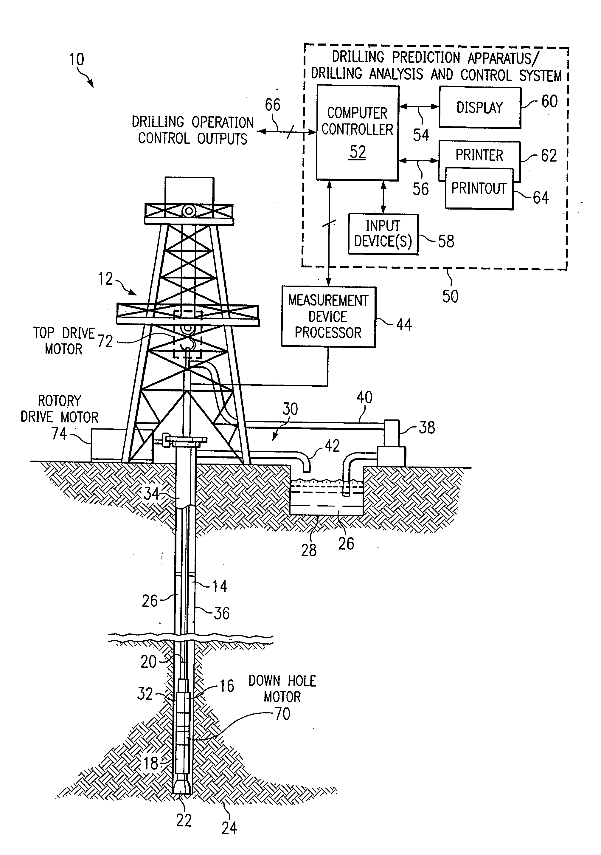
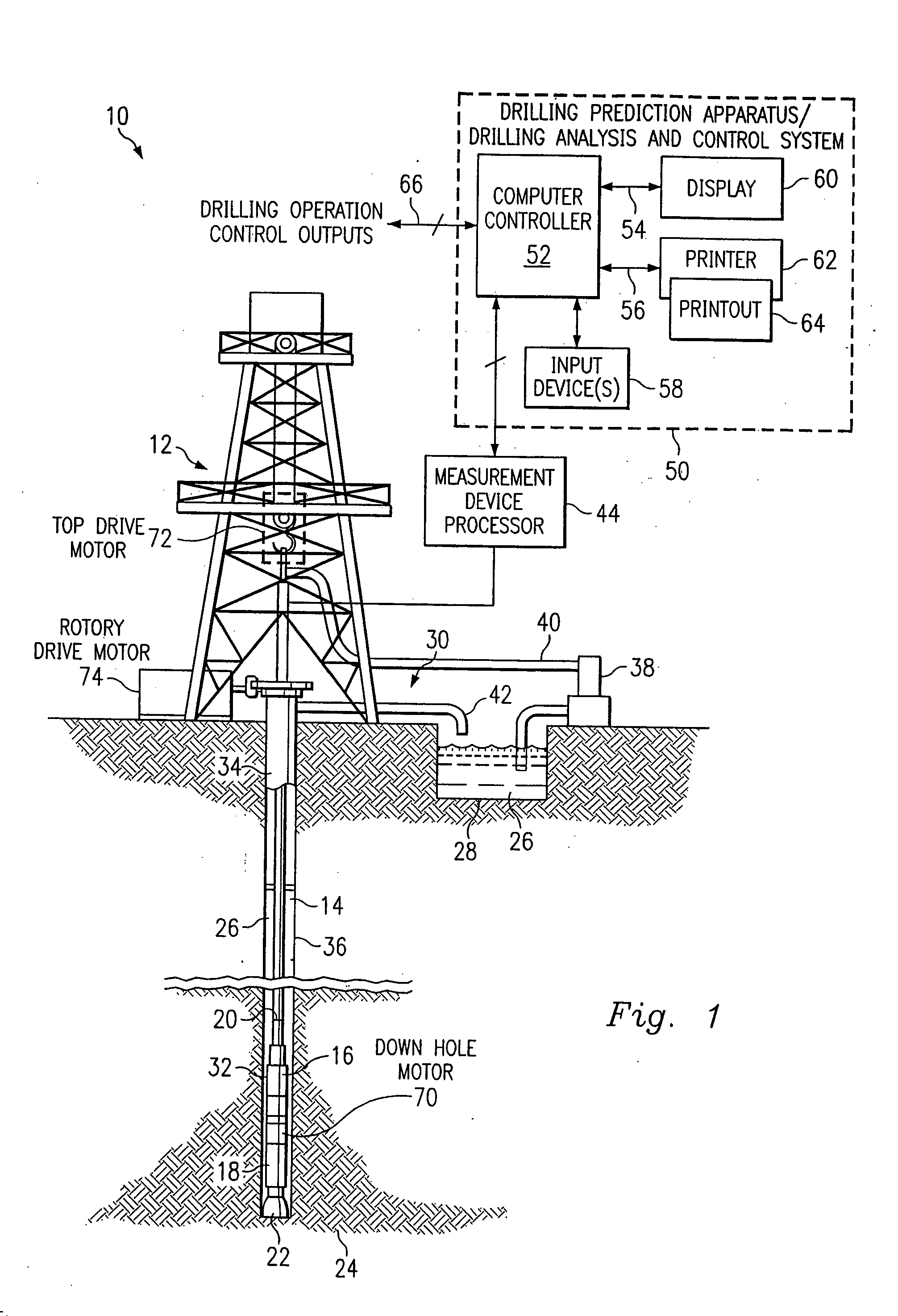
[0023] Referring now to FIG. 1, a drilling system 10 includes a drilling rig 12 disposed atop a borehole 14. A logging tool 16 is carried by a sub 18, typically a drill collar, incorporated into a drill string 20 and disposed within the borehole 14. A drill bit 22 is located at the lower end of the drill string 20 and carves a borehole 14 through the earth formations 24. Drilling mud 26 is pumped from a storage reservoir pit 28 near the wellhead 30, down an axial passageway (not illustrated) through the drill string 20, out of apertures in the bit 22 and back to the surface through the annular region 32. Metal casing 34 is positioned in the borehole 14 above the drill bit 22 for maintaining the integrity of an upper portion of the borehole 14.

[0024] With reference still to FIG. 1, the annular 32 between the drill stem 20, sub 18, and the sidewalls 36 of the borehole 14 forms the return flow path for the drilling mud. Mud is pumped from the storage pit near the well head 30 by pumpi...


PUM


Abstract

A method and apparatus for predicting the performance of a drilling system for the drilling of a well bore in a given formation includes generating a geology characteristic of the formation per unit depth according to a prescribed geology model, obtaining specifications of proposed drilling equipment for use in the drilling of the well bore, and predicting a drilling mechanics in response to the specifications as a function of the geology characteristic per unit depth according to a prescribed drilling mechanics model. Responsive to a predicted drilling mechanics, a controller controls a parameter in the drilling of the well bore. The geology characteristic includes at least rock strength. The specifications include at least a bit specification of a recommended drill bit. Lastly, the predicted drilling mechanics include at least one of bit wear, mechanical efficiency, power, and operating parameters. A display is provided for generating a display of the geology characteristic and predicted drilling mechanics per unit depth, including either a display monitor or a printer.

Description

CROSS REFERENCE TO CO-PENDING APPLICATION(S) [0001] This application is a continuation-in-part of U.S. patent application Ser. No. 09 / 192,389, filed on Nov. 13, 1998, which is a continuation-in-part of U.S. patent application Ser. No. 09 / 048,360, filed on Mar. 26, 1998, which is a continuation-in-part of U.S. patent application Ser. No. 08 / 621,411, filed on Mar. 25, 1996, now U.S. Pat. No. 5,794,720. The co-pending application and issued patent are incorporated herein by reference in their entirety.BACKGROUND OF THE INVENTION [0002] 1. Field of the Invention [0003] The present invention is related to earth formation drilling operations, and more particularly, to methods and system apparatus for predicting performance of a drilling system for a given formation. [0004] 2. Discussion of the Related Art [0005] From the very beginning of the oil and gas well drilling industry, as we know it, one of the biggest challenges has been the fact that it is impossible to actually see what is goi...

Claims


Application Information

Patent Timeline
29 Dec 2005
Publication
US20050284661A1
IPC
E21B12/02; E21B41/00; E21B44/00; E21B49/00
CPC
E21B12/02; E21B44/00; E21B2041/0028; E21B49/00; E21B49/003; E21B44/005; E21B2200/22
Inventors
GOLDMAN, WILLIAM A.; MATTHEWS, OLIVER III