Neck gripping conveyor and link, and related rotary filler and system

a conveyor and link technology, applied in the direction of filling without pressure, furnaces, charging manipulation, etc., can solve the problems of occupying valuable floor space in use, requiring a great amount of storage space, maintenance and upkeep, and extra (unused) star wheels and/or sets of star wheels

Inactive Publication Date: 2005-12-29
ILLINOIS TOOL WORKS INC
View PDF99 Cites 27 Cited by
  • Summary
  • Abstract
  • Description
  • Claims
  • Application Information

AI Technical Summary

Benefits of technology

[0016] For example, the guide structure may be an opening defined through the link, and the opening may be configured for aligning a container with a component of one or more of a filler, a capper, a labeler or ...

Problems solved by technology

Also, the star wheel assemblies take up valuable floor space in use, as a typical star wheel may be, for example, 4 feet in diameter.
The extra (unused) star wheels and/or sets of star wheels thus require a great amount of storage space.
The star wheels also require maintenance and upkeep, and generally add to the overall cost of the filling operation.
To accomplish multiple parallel row filling operations with conventional star wheel indexing technology would require complicated and expensive gearing and drive arrangements and is not considered commercially viable.
The linear-type machines, however, also have drawbacks, particularly with respect to processing speed.
Doing so requires a certain amount of machinery and space.
Also, in such systems the containers are at some points of travel not held fast to one part of the system machinery or another, potentially leading to toppling over or breaking of containers, as has been experienced with various other filling machines and systems over the years.
While the conveyors disclosed in U.S. Pat. No. 6,209,716 work well for ...

Method used


Image

  • Neck gripping conveyor and link, and related rotary filler and system
  • Neck gripping conveyor and link, and related rotary filler and system
  • Neck gripping conveyor and link, and related rotary filler and system

Examples


Embodiment Construction

[0048] Reference will now be made in detail to embodiments of the invention, one or more examples of which are illustrated in the drawings. Each example is provided by way of explanation of the invention, and not meant as a limitation of the invention. For example, features illustrated or described as part of one embodiment can be used with another embodiment to yield still a third embodiment. It is intended that the present invention include these and other modifications and variations. In discussing various embodiments, like or similar reference numerals are used below with like or similar parts of various embodiments.

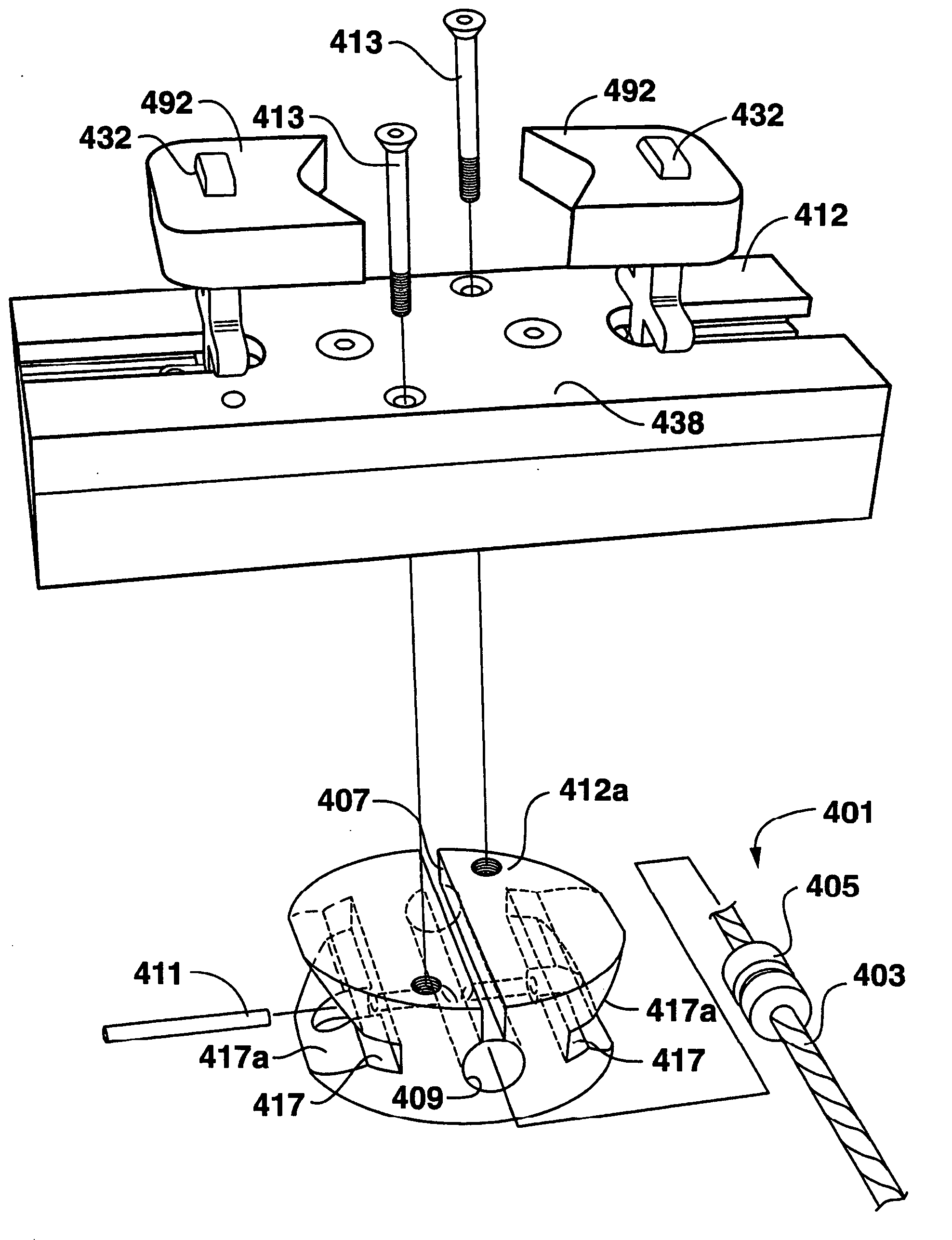
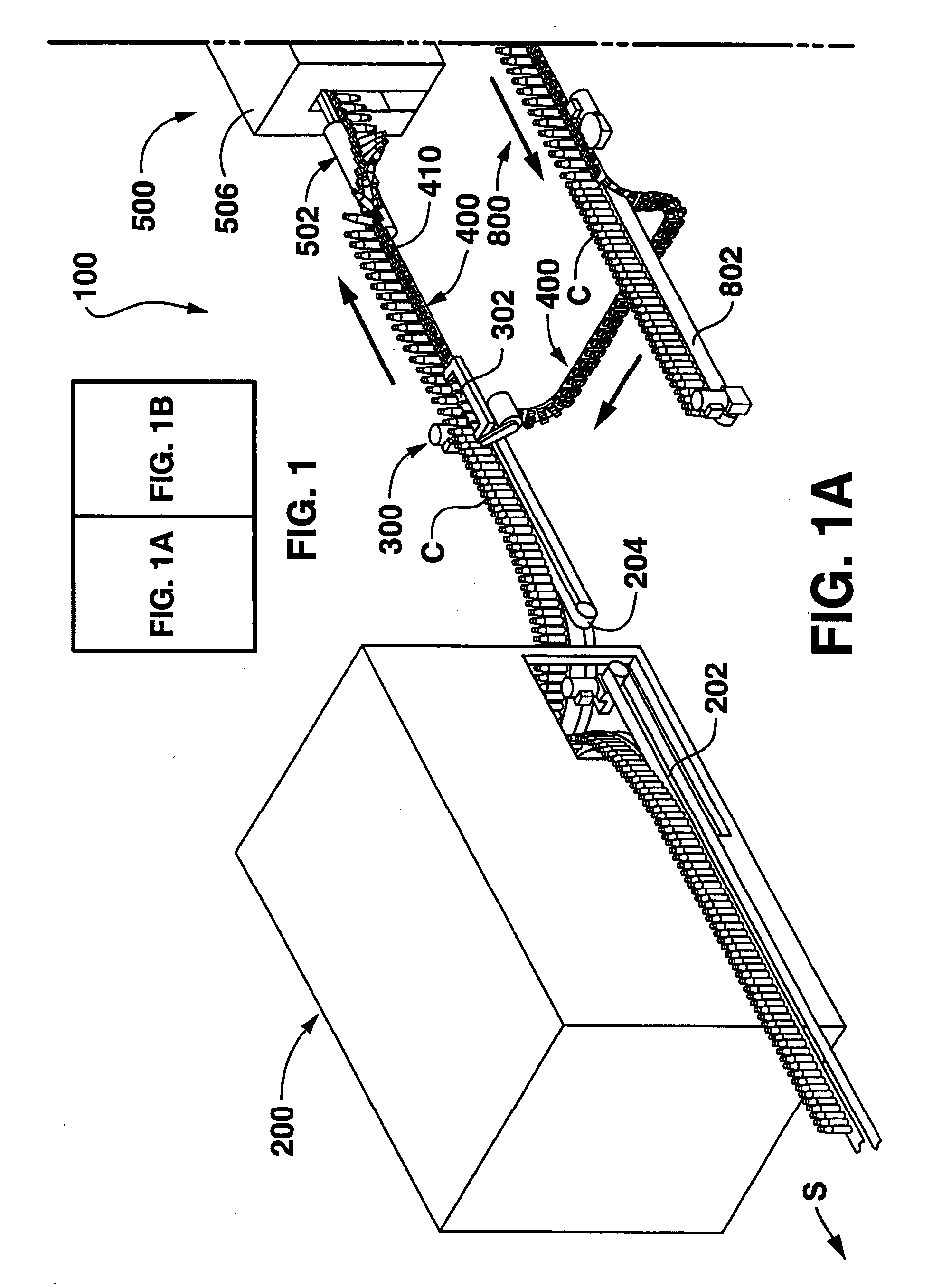
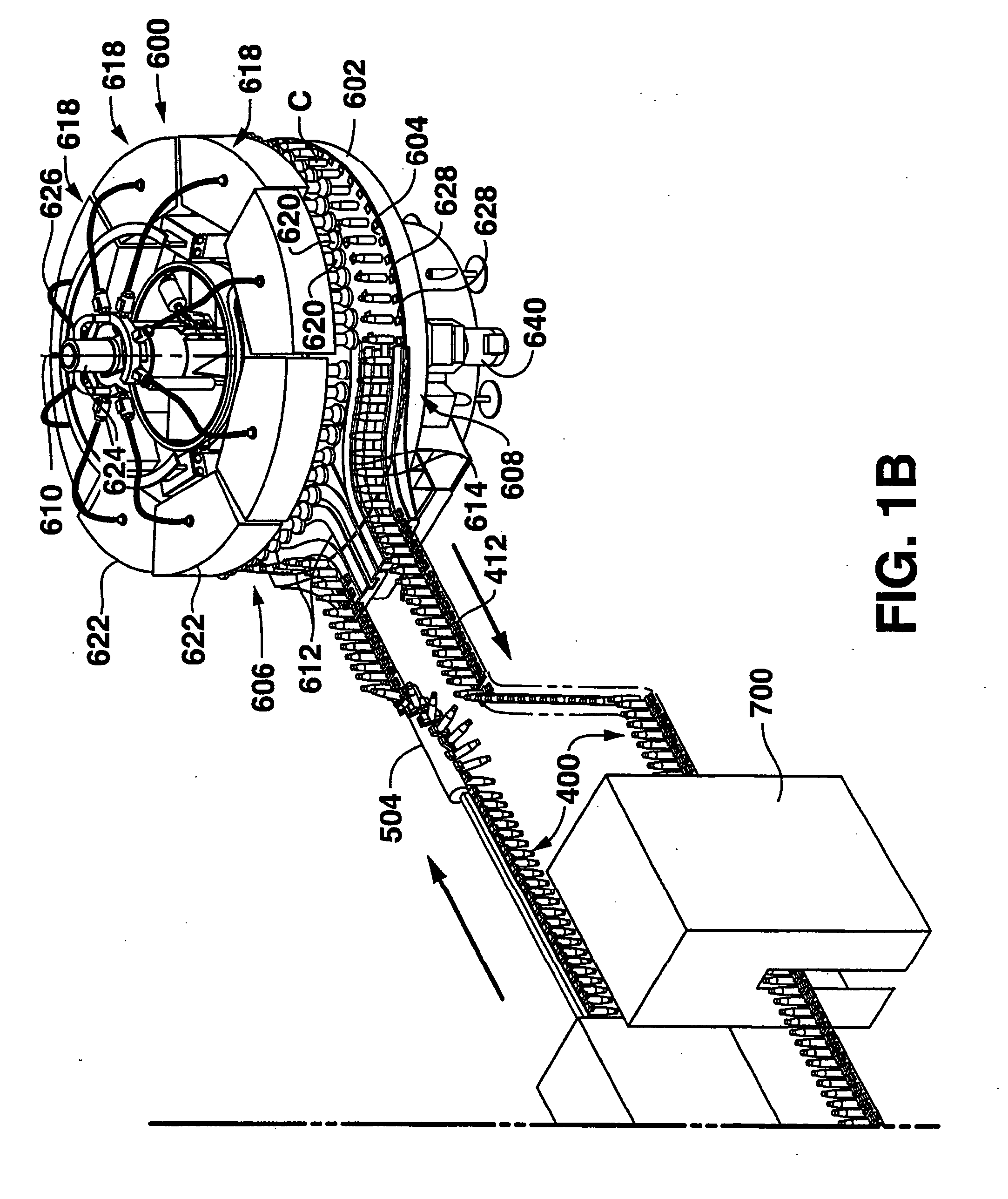
[0049] As shown in the various figures, embodiments of a flexible conveyor having links, and flexible connection elements for conveyors, along with their constituent parts, are disclosed. It should be understood that the present invention encompasses both a full conveyor structure made of individual links, connecting structures, and / or other components, and individu...


PUM


Abstract

A conveyor is disclosed suitable for conveying objects such as containers to a processing station. The conveyor includes a plurality of connected links, and at least one gripping member extending from each of the links. Each gripping member is movable relative to its respective link for gripping a container by the neck of the container. A guide structure is disposed on the link for mating a component of the processing station to the neck of the container for processing the container. The processing station may be a filler such as a rotary filler, a capper, or a rinser. Related individual links, conveying systems, and filler components are also disclosed.

Description

RELATED APPLICATION [0001] The present application is a continuation-in-part application claiming priority under 35 U.S.C. § 120 to U.S. patent application Ser. No. 10 / 879,690, filed Jun. 29, 2004, and incorporated by reference herein.FIELD OF THE INVENTION [0002] The present invention relates generally to neck-gripping conveyor designs and related components such as conveyor links. Other aspects relate to use of such conveyors in rotary fillers and along conveying systems. BACKGROUND OF THE INVENTION [0003] Automated filling machines configured for filling any manner of container processed through the machine by a conveyor or the like are old and well known in the art. For example, a conventional high-speed filling machine typically uses a worm gear or screw-like device to orient and deliver containers (i.e., bottles) conveyed in single file and in contact with each other. The worm gear engages each container and spaces the containers apart a desired distance corresponding to the s...

Claims


Application Information

Patent Timeline
IPC IPC(8): B65G17/30B65G17/38B65G17/42B67C3/04B67C3/06B67C3/24B67C3/26B67C7/00
CPCB67C3/225B67C3/06B67C3/2637B67C7/004B67C2003/266B67C2003/2677B65G17/323B65G17/385B65G17/42B65G47/842B65G2201/0235B65G2201/0244B65G2201/0247B67C3/04B67C3/242
Inventor HARTNESS, THOMAS P.HARTNESS, WILLIAM R. IIIDAVIDSON, MARK W.BRENNAN, FRANKBEESLEY, ROBERT C.
Owner ILLINOIS TOOL WORKS INC
Why Eureka
Try Eureka