Sheet supply device

Inactive Publication Date: 2005-12-29
FUJIFILM BUSINESS INNOVATION CORP
View PDF1 Cites 32 Cited by
  • Summary
  • Abstract
  • Description
  • Claims
  • Application Information

AI Technical Summary

Benefits of technology

[0024] According to this aspect, the height of the upper end of the air blocking member is set to be higher when the sheets are being fed than when the sheets are not being fed. As a result, the function of the fifth aspect is effectively achieved.
[0025] In short, according to the present invention, even when the air is blown so as to release the adhesion bet

Problems solved by technology

Therefore, even when a sheet is fed with the surface thereof rubbing against members above the sheets such as a regula

Method used


Image

  • Sheet supply device
  • Sheet supply device
  • Sheet supply device

Examples


Embodiment Construction

[0040] An image forming apparatus having a sheet supply device according to embodiments of the present invention will be explained below with reference to the drawings. As an image forming system in the image forming apparatus, a known electrophotographic process is used.

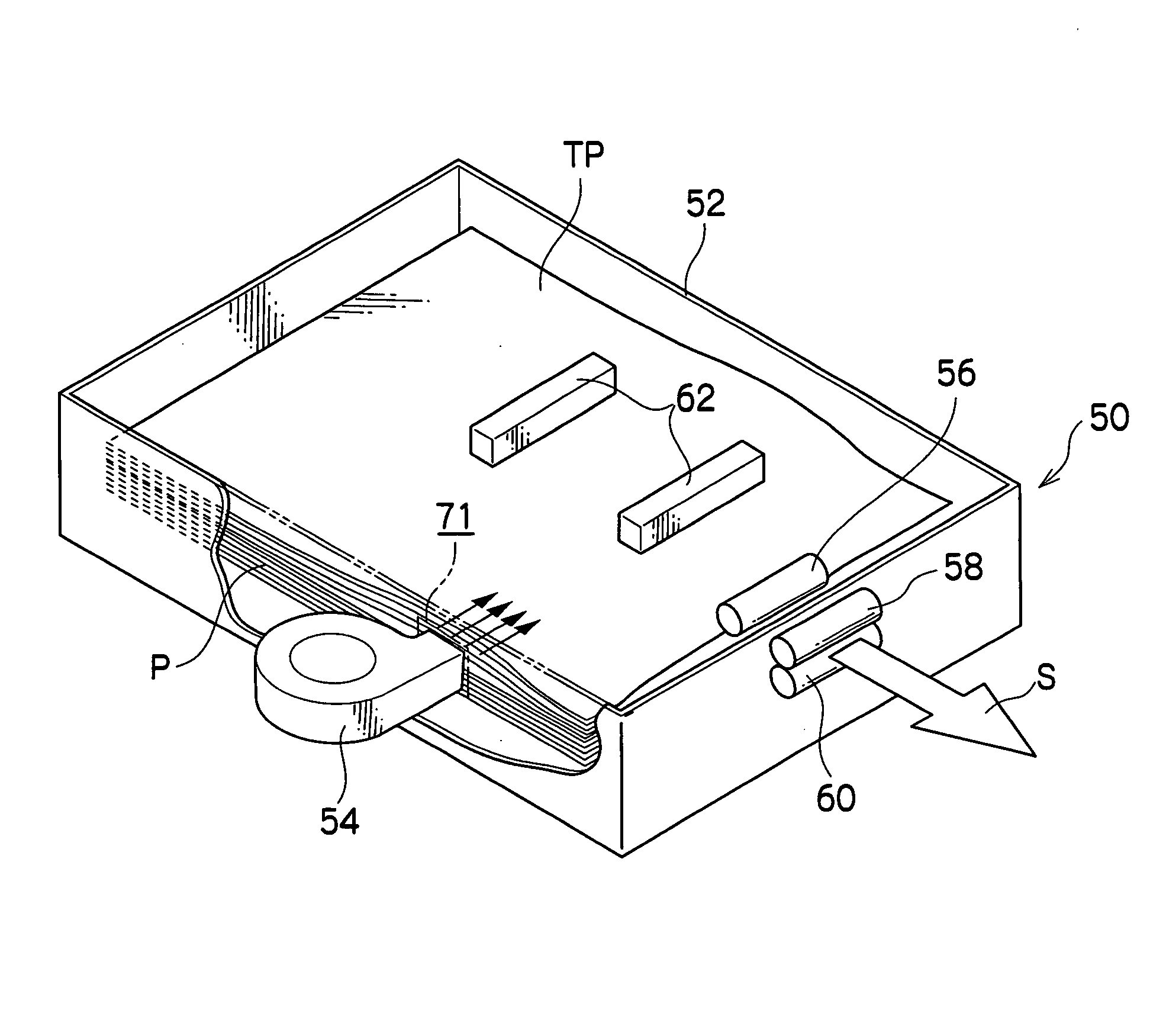
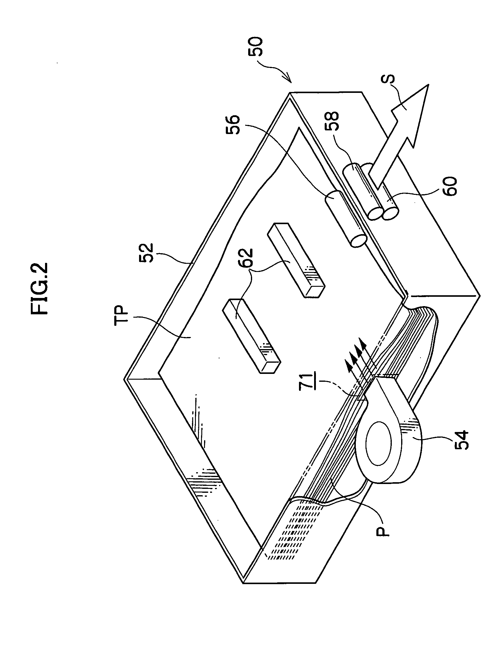
[0041] A structure of the image forming apparatus 10 and a summary of image formation will be described first, and a main section of the invention will be explained thereafter. As sheets P on which an image is formed, sheets with a smooth surface are used such as normal paper or coated paper, the surface of which undergoes a coating process in order to provide whiteness and gloss.

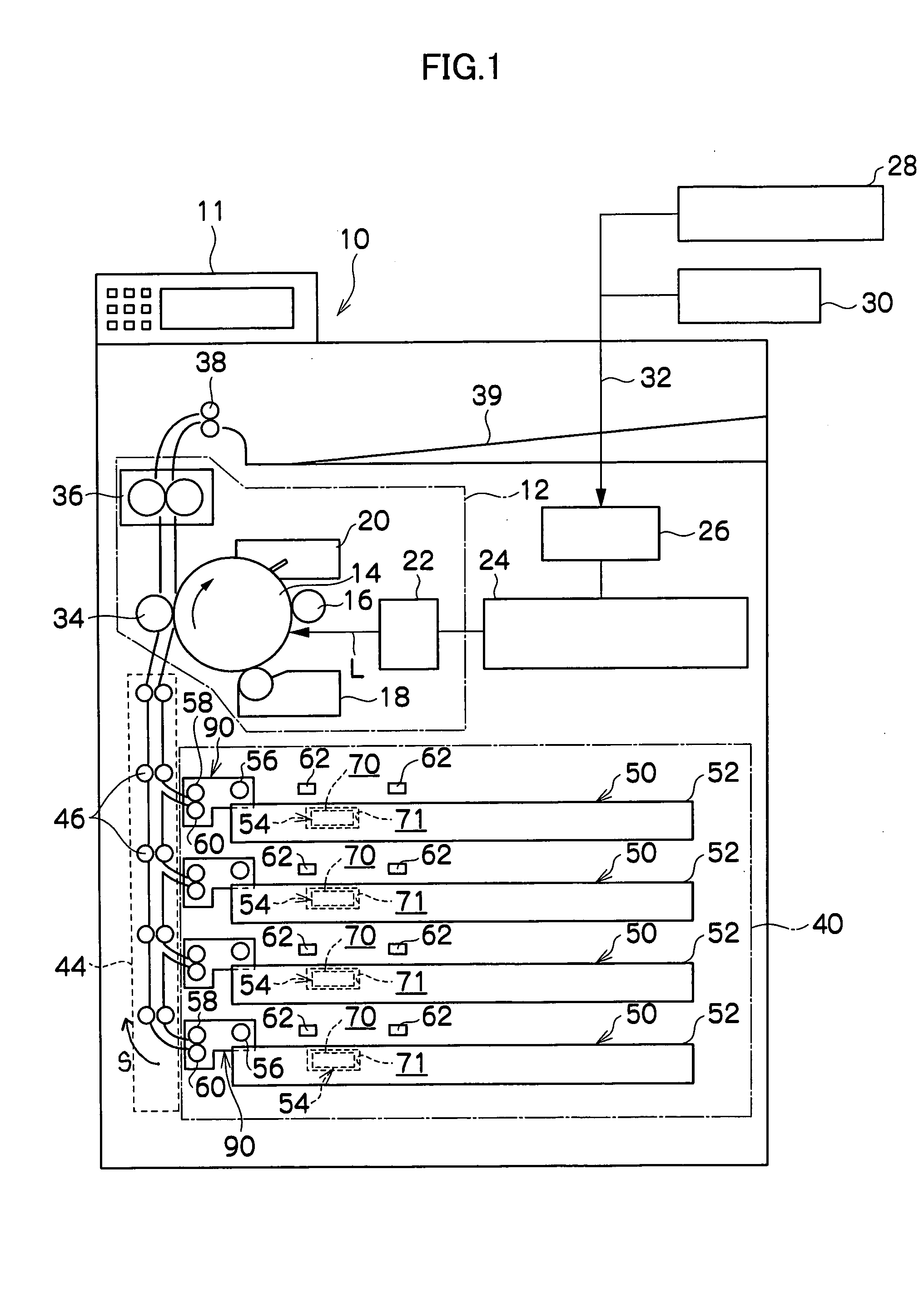
[0042] As shown in FIG. 1, the image forming apparatus 10 has a control unit 24 that controls the entire image forming apparatus 10 and stores various information therein. An operation panel 11 is provided on an upper portion of the apparatus. When a user operates the operation panel 11, the control unit 24 controls the apparatus in accor...


PUM


Abstract

A sheet supply device has a sheet storing section on which sheets are stacked and stored, a sheet feed unit that feeds the sheets stored in the sheet storing section to a next process, and an air blower that blows air to the sheets stored in the sheet storing section. A force for pushing up the sheets, which is exerted on the sheets by the blown air, is set to be weaker when the sheets are being fed than when they are not being fed.

Description

CROSS-REFERENCE TO RELATED APPLICATION [0001] This application claims priority under 35 USC 119 from Japanese Patent Application No. 2004-191549, the disclosure of which is incorporated by reference herein. BACKGROUND OF THE INVENTION [0002] 1. Field of the Invention [0003] The present invention relates to a sheet supply device. [0004] 2. Description of the Related Art [0005] Conventionally, image forming apparatuses such as printers and copying machines generally use cut sheets (copying paper) as a medium on which an image is formed, which cut sheets enable continuous supply. Hitherto, plain paper and woodfree paper specified by manufacturers of copying machines have been used as these sheets (paper). [0006] Plain paper and woodfree paper have low smoothness, and thus have weak adhesion. It is thus relatively easily to prevent so-called double feed wherein when sheets are to be supplied one by one from a sheet stacking section such as a sheet feed tray, a plurality of sheets are fe...

Claims


Application Information

Patent Timeline
IPC IPC(8): B65H3/14B65H3/48B65H5/02B65H5/04
CPCB65H3/48B65H2513/40B65H2515/212B65H2220/01B65H2220/02B65H2515/20
Inventor UJI, NOBUTAKAFUJIKURA, HIROAKI
Owner FUJIFILM BUSINESS INNOVATION CORP
Why Eureka
Try Eureka