Wheel traceability system

a technology of tracing system and wheel, which is applied to disc wheels, vehicle components, rims, etc., can solve the problems of ink stamping, inability to accurately identify the wheel, and inability to accurately mark the wheel, so as to tightly control inventory and quality, and efficiently address quality control problems.

Inactive Publication Date: 2005-12-29
SUPERIOR INDS INT
View PDF13 Cites 18 Cited by
  • Summary
  • Abstract
  • Description
  • Claims
  • Application Information

AI Technical Summary

Benefits of technology

[0007] The present invention provides for the permanent marking of automotive roadwheels so as to render each wheel individually identifiable throughout the process of its manufacture as well as throughout its service life. Such identification system provides benefits for the wheel manufacturer and the automobile manufacturer as well as the end user. The wheel manufacturer is thereby able to gain the ability to more tightly control inventory, to monitor progress throughout each wheel's various manufacturing steps, and to more efficiently address quality control issues both before and after distribution of the finished wheel. The automobile manufacturer in turn thereby similarly stands to gain the ability to more tightly control inventory as well as quality. Once in service, additional benefits are realizable to the extent that should a wheel fail, the specifics of its manufacturing history can easily be traced. Conversely, should a recall of wheels become necessary, individual automobiles to which the wheels have actually been mounted can readily be identified for recall by correlating wheel IDs with VINs, thereby obviating the need to recall an excess number of automobiles in order to ensure full recovery of the defective wheels. A uniquely identified wheel can additionally provide benefit with regard to theft deterrence as a mutilated or defaced wheel ID or one that is altered and fails to correlate to the VIN of the vehicle to which it is mounted would invite investigation and may therefore have an adverse effect on the market for stolen wheels.
[0008] A wheel manufactured in accordance with the present invention, has a unique identifying marking formed therein, applied thereto or otherwise disposed thereon as early in the manufacturing process as possible, preferably immediately after the casting step. In a preferred embodiment, the raw casting includes at least one cast-in recess wherein such recess is dimensioned to receive the identifying marking. The recess is formed in a location that serves to protect the identifying marking during the manufacturing process and with sufficient depth to preclude contact between the identifying marking and the machining tools that are brought to bear against the casting during the machining process. The location of the recess is additionally selected so as to ensure that the identifying marking is protected during the service life of the wheel. Most preferably, the recess is located on the wheel's tire side and more specifically on the side of the drop center. Such location is preferred as it is consistent from wheel design to wheel design and thereby facilitates both the marking of the wheel as well as the subsequent the reading of the marking. Moreover, because this area of the wheel will become covered by the tire that is mounted to the wheel, the marking will be protected from the elements and should remain readable throughout the wheel's service life. This location also serves to preserve the aesthetics of the wheel as it will be hidden from view due to the presence of the tire. An additional benefit associated with this location is that a thief would have to expend the effort to separate the wheel and tire to alter or obliterate the marking or to merely check for the presence of an identifying marking to thereby further deter at least the casual thief.
[0009] The present invention additionally provides for two such recesses to be formed in the wheel casting, preferably in the side of the drop center and preferably spaced apart by 180°. The 180° spacing has the effect of automatically canceling any adverse effect a single recess may have on the balance of the wheel. The accommodation of two markings is additionally beneficial to the extent that a redundancy ensures that the wheel continues to be identifiable should one marking be or become unreadable. Additionally, the application of two markings allows two different systems to be used, for example one that is machine readable such as for example a bar code and a second that is readable without a machine such as an alphanumeric designation. This thwarts alteration as a discrepancy between an altered alphanumeric designation and a non-corresponding bar code would be ascertainable.
[0013] The location of the identifying mark within the recess formed in the side of the drop center serves to protect the mark during machining process wherein the mark is located at a depth below the anticipated cut imparted to the surrounding surface during the machining process. During the application of paint, the marking may be temporarily masked or its three dimensional character may be sufficient to ensure readability despite coatings of paint. The location of the marking within a recess on the side of drop center also protects the marking during the tire mounting operation as the tire bead is supported by the surrounding surface as it is drawn there across to the bead seat.

Problems solved by technology

However, while such system could theoretically prevent, for example, a raw casting from inadvertently being passed on to a machining step without having undergone an inspection or from inadvertently being finished prior to heat treatment, a number of disadvantages are nonetheless inherent therein.
Reliance on a series of stamps in an effort to control the manufacturing process can be susceptible to operator error or abuse to the extent that the absence of a stamp may be overlooked or ignored or a stamp that is visible may be misinterpreted.
Additionally, the steel or ink stamping of wheels is rather labor intensive, certain wheels are difficult to stamp due to wheel geometry and the resulting marking may not be legible or only partially legible.
This dearth of information substantially frustrates attempts to trace with any precision a wheel's manufacturing history or its whereabouts during its service life.
Conversely, if a failure during the service life of a wheel indicates that a manufacturing defect may be involved, the circumstances of that particular wheel's manufacture would not be ascertainable and hence, the identification of wheels similarly situated would be very difficult.
Due to the high cost of modern alloy wheels, such wheels are susceptible to theft.

Method used


Image

  • Wheel traceability system
  • Wheel traceability system
  • Wheel traceability system

Examples


Embodiment Construction

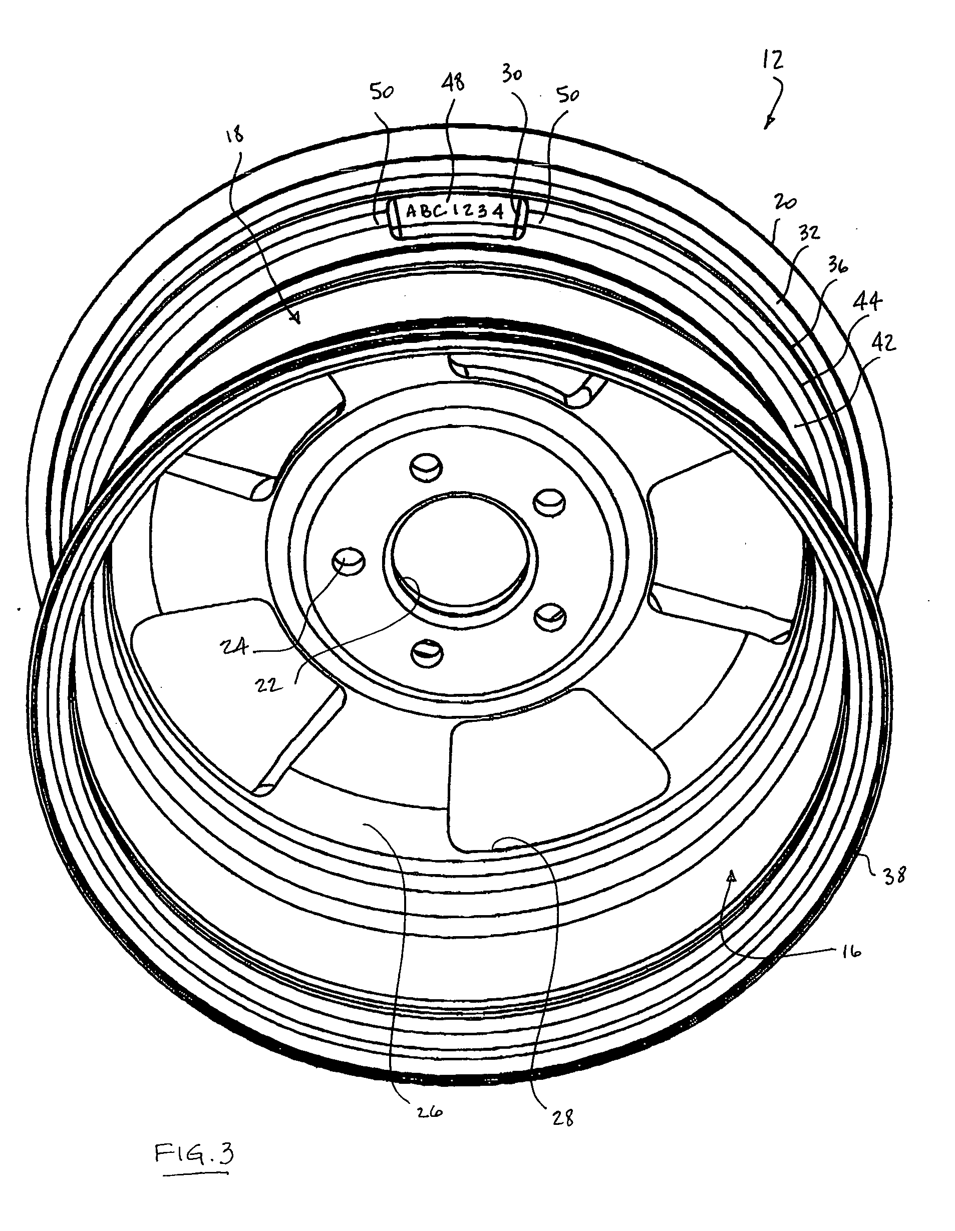
[0018] The present invention provides for the application of a unique identifying marking to an automotive roadwheel as early during the manufacturing process as is practicable and in such a manner so as to ensure that the marking remains legible throughout the balance of the process as well as throughout its service life. By imparting a unique identity to each wheel, the progress of each wheel through its manufacturing process can be monitored, controlled and memorialized and its path through the stream of commerce can be traced. By matching wheel ID with the VIN of the vehicle to which it was mounted, the end user of a particular wheel can be identified, and conversely, the manufacturing history of a particular end user's wheel can be summoned. The following description is directed to one preferred embodiment of the present invention.

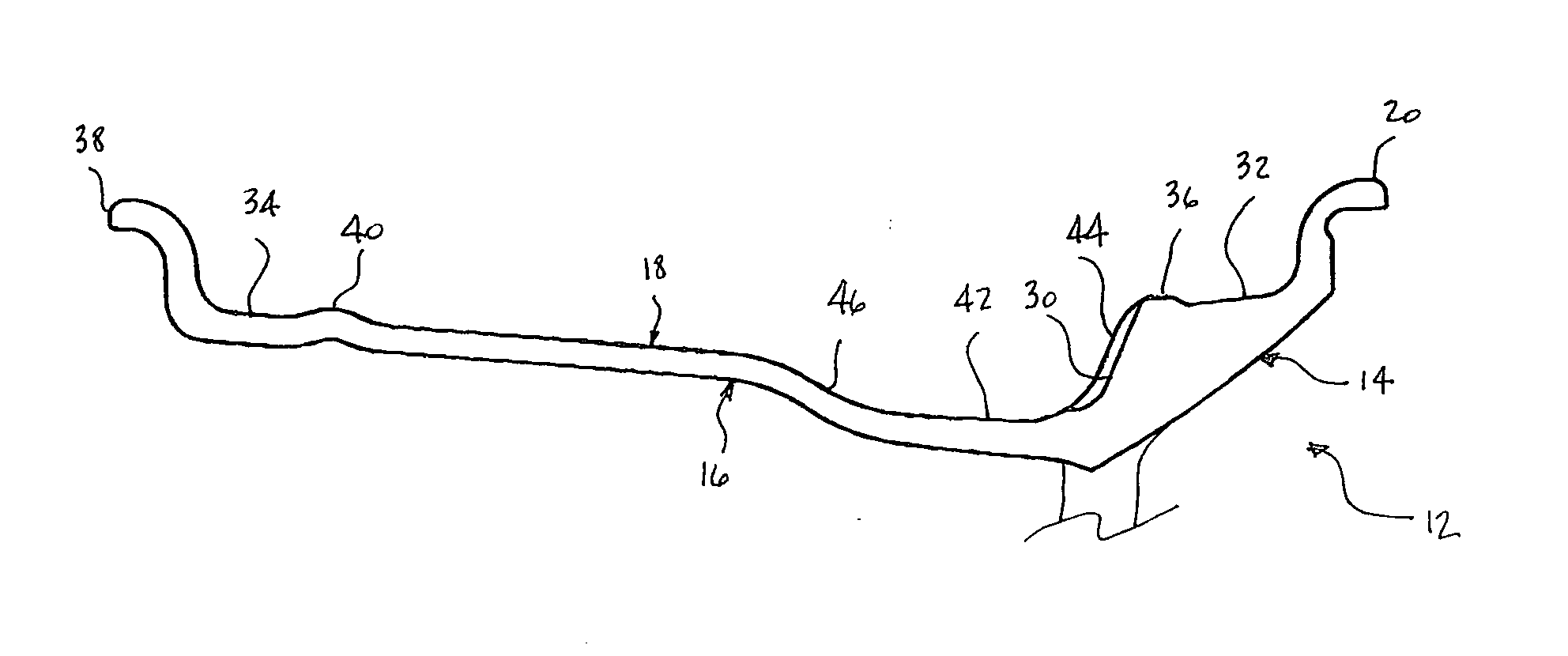
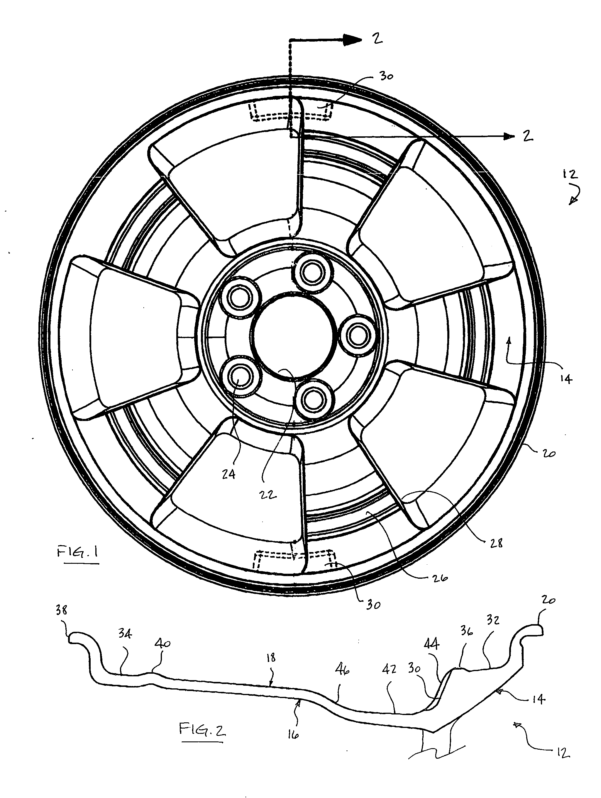
[0019]FIG. 1 is a curb-side view of a wheel 12 of the present invention. A roadwheel's curb side 14 is that which is visible when mounted on a vehic...


PUM


Abstract

An identifying mark is disposed in a cast-in recess that is formed in a raw casting that is subsequently transformed into an automotive roadwheel. The mark provides for a unique identification to thereby allow the progress of each wheel through its manufacturing process to be monitored and its manufacturing history to be memorialized. The same identifying mark may be relied upon by the auto manufacturer for similar purposes and by matching each wheel's ID to VIN of the vehicle to which it is mounted, the end user should remain traceable throughout the wheel's service life. The recess is positioned so as to protect the mark disposed therein during the manufacturing process as well during its end use.

Description

FIELD OF THE INVENTION [0001] The present invention generally relates to an identification system for automotive roadwheels and more particularly pertains to the marking of wheels so as to render each wheel uniquely identifiable during its manufacturing process as well as throughout its service life. BACKGROUND OF THE INVENTION [0002] The process for manufacturing cast automotive roadwheels involves a large number of steps including, but not limited to, steps relating to casting, machining, heat treating and finishing as well as a multitude of quality control inspections that are performed throughout the process. In an effort to control the progression of the manufacturing process, some wheel manufacturers rely on various stamps that are applied to the wheel after certain steps or inspections have been completed. By requiring a particular mark to be present before a successive step will be undertaken, some control over the entire process is achievable. However, while such system cou...

Claims


Application Information

Patent Timeline
Patent Type & Authority Applications(United States)
IPC IPC(8): B60B3/10B60B21/06
CPCB60B21/023B60B21/028B60B21/026
Inventor BAL, PUSHPINDER SINGH
Owner SUPERIOR INDS INT
Why Eureka
Try Eureka