Linear motor geometry for use with persistent current magnets

a technology of persistent current magnets and linear motors, applied in the direction of dynamo-electric components, dynamo-electric machines, white arms/cold weapons, etc., can solve the problems of preventing the realization of such launch apparatuses or vehicles

Active Publication Date: 2005-12-29
HOUSTON SYST UNIV THE
View PDF4 Cites 11 Cited by
  • Summary
  • Abstract
  • Description
  • Claims
  • Application Information

AI Technical Summary

Benefits of technology

[0009] The invention is an electrically powered launcher that can

Problems solved by technology

The possibility of using electrically powered or electromagnetic (EM) launch apparatus to drastically reduce the cost of placing small payloads in orbit or to deliver

Method used


Image

  • Linear motor geometry for use with persistent current magnets
  • Linear motor geometry for use with persistent current magnets
  • Linear motor geometry for use with persistent current magnets

Examples


Embodiment Construction

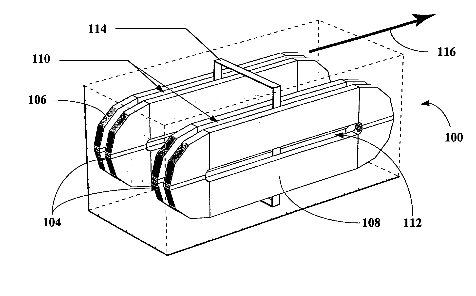
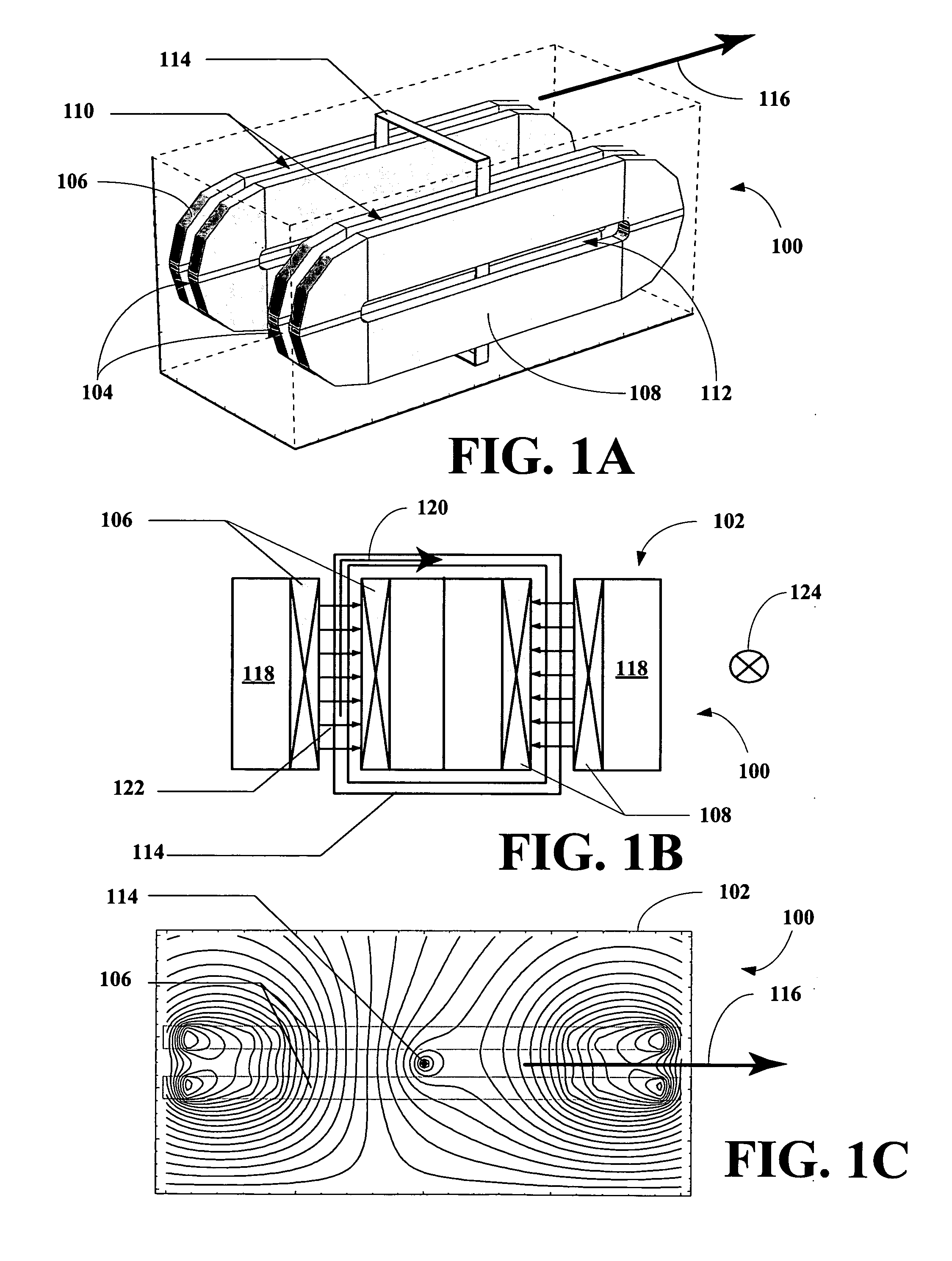
[0028] The inventors have found that a linear motor can be constructed using superconducting materials that allow the motor to be used as a launching platform for payloads, where the platform can accelerate the payloads to orbital or sub-orbital velocities. The launching platform is, thus, ideally suited for delivery payloads into space or for other application requiring linear acceleration such as electromagnetic guns, cannons, or rocket launchers.

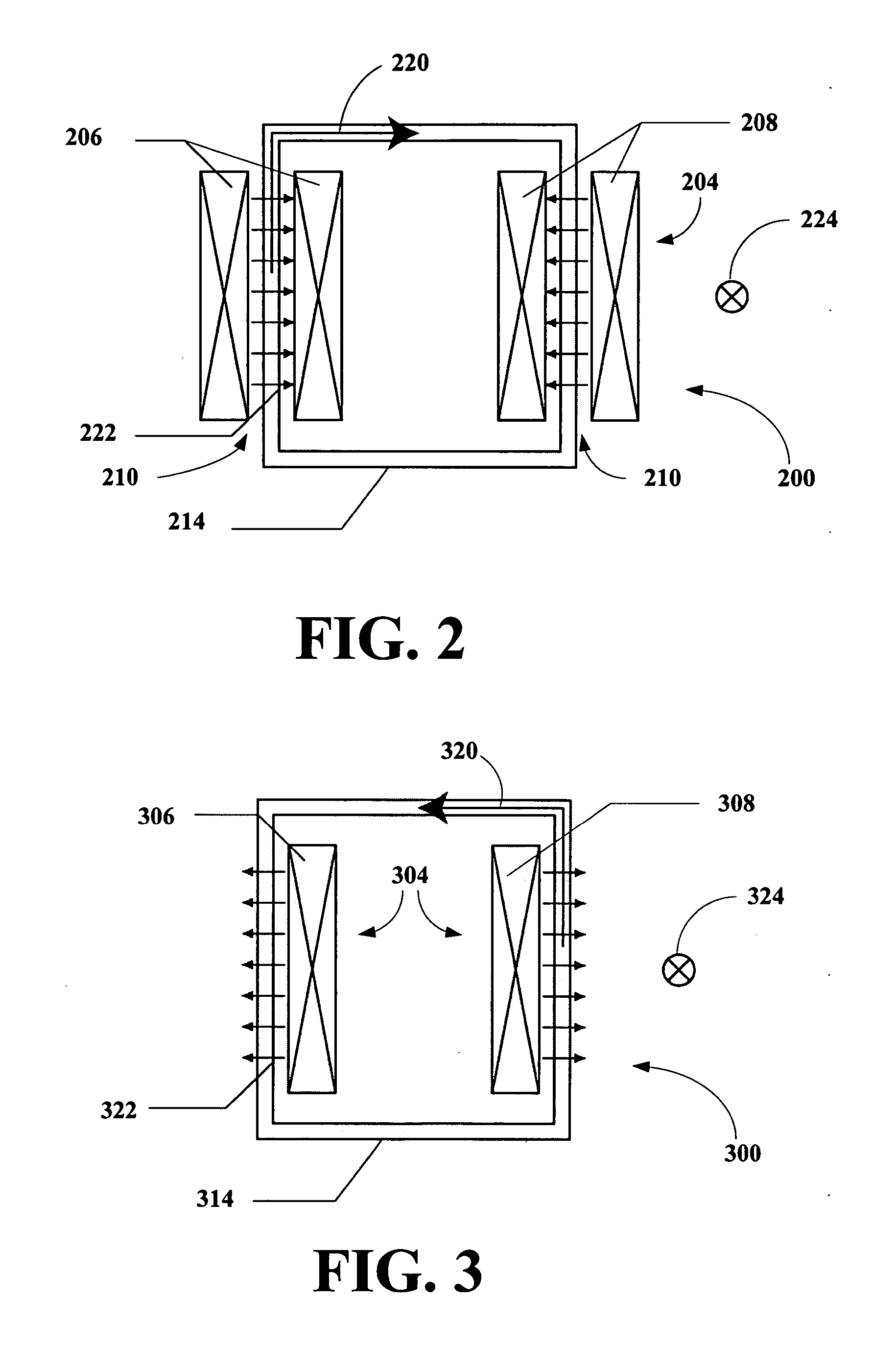
[0029] The geometry of the Linear Persistent Current Motor (LPCM) apparatus of this invention is related to existing EM launch concepts. The motor apparatus of this invention includes a wound-secondary with the secondary turned by 90 degrees. The motor apparatus of this invention is similar to an apparatus having two augmented railguns operating in parallel, but with links connecting the railgun armature segments.

[0030] The geometry of the LPCM apparatus of this invention has the following advantages: (1) a complete loop in the secondar...


PUM


Abstract

An electrically powered launcher is disclosed that can accelerate small payloads to orbital velocities. The invention uses a novel geometry to overcome limitations of other design, and allows full exploitation of existing superconducting materials.

Description

RELATED APPLICATIONS [0001] This application claims provisional priority to U.S. Provisional Patent Application Ser. No. 60 / 578,272, filed 9 Jun. 2004.BACKGROUND OF THE INVENTION [0002] 1. Field of the Invention [0003] The present invention relates to a novel linear motor or linear acceleration apparatus. [0004] More particularly, the represent invention relates to a novel linear motor or acceleration apparatus utilizing superconductors in a persistent current mode for both a primary and secondary assemblies. The motor is well-suited as electromagnetic payload launch apparatus or as a projectile launch apparatus because sliding current pickups are not needed for the secondary assembly, the power supply can be arbitrarily small, and no quench or other switching of the primary assembly is necessary during a launch of a payload. [0005] 2. Description of the Related Art [0006] Currently, electromagnetic (EM) launch apparatuses include superconducting motors such as the quench gun and co...

Claims


Application Information

Patent Timeline
IPC IPC(8): F41B6/00H02K41/00H02K41/035H02K55/00
CPCF41B6/003H02K55/00H02K41/0356H02K41/00Y10S505/876Y10S505/776
Inventor PUTMAN, PHILSALAMA, KAMEL
Owner HOUSTON SYST UNIV THE
Why Eureka
Try Eureka