System and method for locating radio emitters using self-calibrated path loss computation

a radio emitter and computation method technology, applied in direction finders, direction finders using radio waves, instruments, etc., can solve the problems of increased system cost and laborious user-assisted system calibration, and achieve the effect of improving the accuracy of receive signal strength based location systems and reducing complexity

Active Publication Date: 2005-12-29
CISCO TECH INC
View PDF11 Cites 134 Cited by
  • Summary
  • Abstract
  • Description
  • Claims
  • Application Information

AI Technical Summary

Benefits of technology

[0005] Techniques are described herein for reducing the complexity and improving the accuracy of receive signal strength based location systems. The system comprises a plurality of radio sensor devices placed at known positions within a space in which positions of devices are to be estimated. The path loss is measured between all combinations of pairs of radio sensor devices based on a test signal transmitted by each radio sensor device. A path loss model is evaluated to compute modeled path loss data between all combinations of pairs of radio sensor devices. For each measured path loss, a path loss error rela

Problems solved by technology

In particular, some receive signal strength location techniques heretofore known require laborious user assisted calibration o

Method used


Image

  • System and method for locating radio emitters using self-calibrated path loss computation
  • System and method for locating radio emitters using self-calibrated path loss computation
  • System and method for locating radio emitters using self-calibrated path loss computation

Examples


Embodiment Construction

[0018] The position / location estimation system and method described herein uses received signal strength (RSS) of the signal emitted by the device to be located (target device) and does not require the aforementioned laborious offline calibration or imported coverage maps. The algorithm may be implemented in two phases, an offline phase for sensor self-calibration, and an online phase for real-time position estimation.

[0019] The System in General

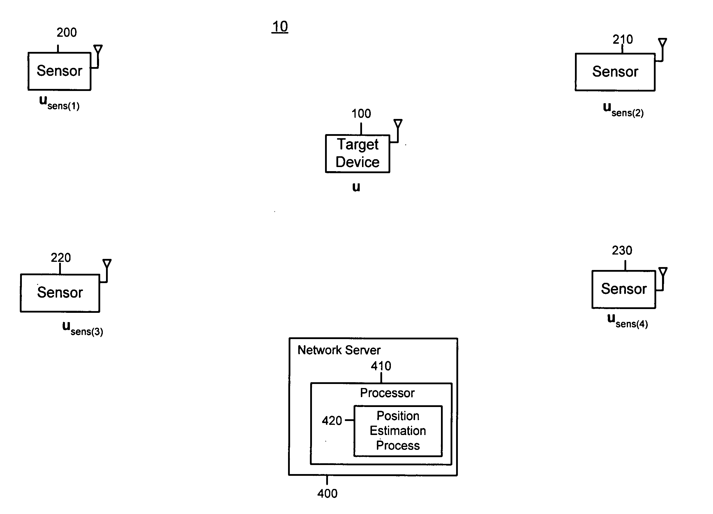
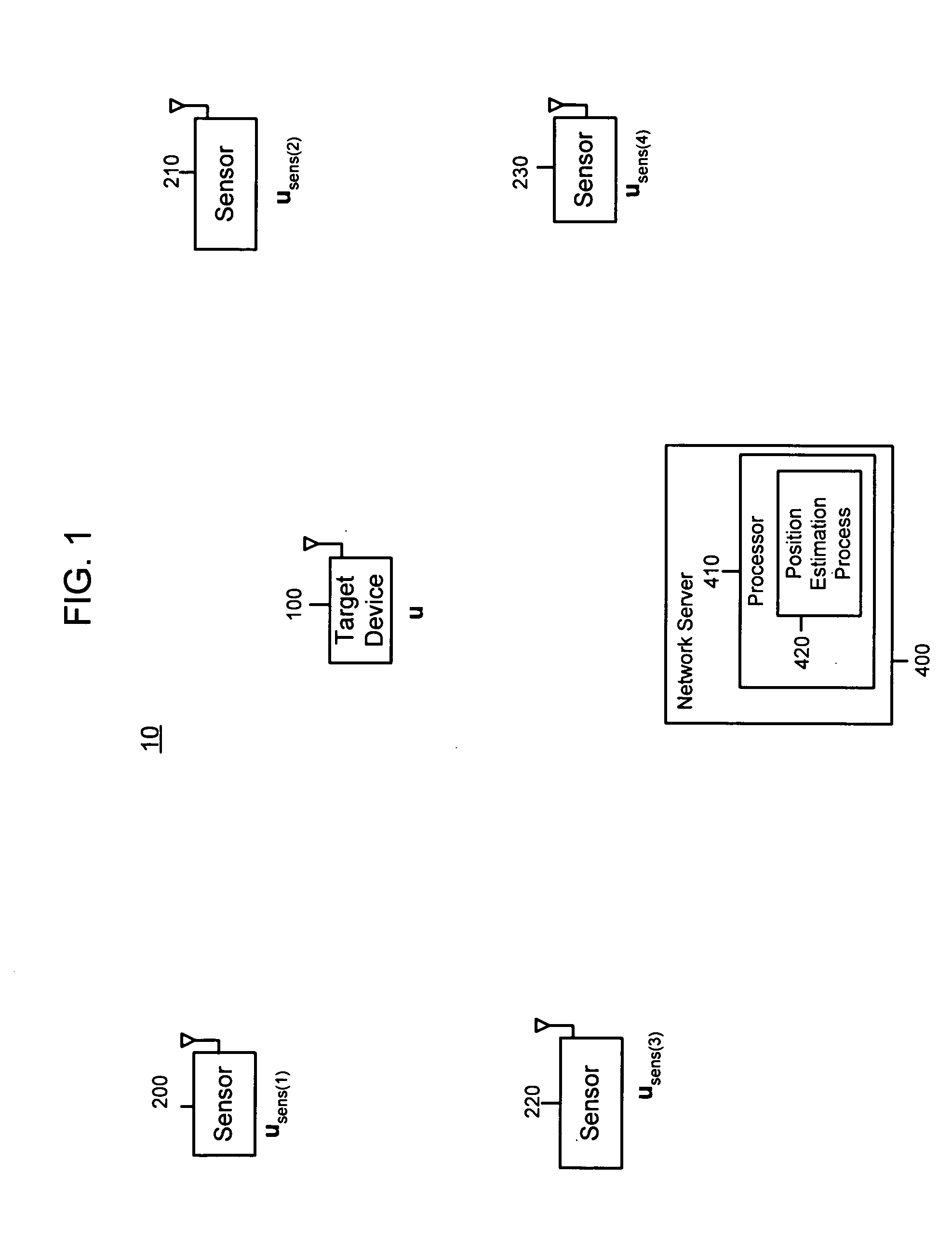
[0020] With reference to FIG. 1, a system 10 is shown comprising a plurality of radio sensor devices (sensors) 200, 210, 220 and 230 and a server computer 400. The sensors are deployed at known positions. Sensors can both transmit and receive signals from each other and receive signals from the device to be located, called a target device 100. For example, sensor 200 is at position usens1, sensor 210 is at position usens2, sensor 220 is at position usens3 and sensor 230 is at position usens4. An example of a sensor is described hereinafter...


PUM


Abstract

Techniques for reducing the complexity and improving the accuracy of receive signal strength based location systems. The system comprises a plurality of radio sensor devices placed at known positions within a space in which devices are to be located. According to one technique, the path loss is measured between all combinations of pairs of radio sensor devices based on a test signal transmitted by each radio sensor device. A path loss model is evaluated to compute modeled path loss data between all combinations of pairs of radio sensor devices. For each measured path loss, a path loss error relative to each radio sensor device is computed by taking the difference between the measured path loss and the modeled path loss. The path loss error relative to each radio sensor device at any candidate position is interpolated from the computed path loss errors. A path loss estimate between a candidate position and each radio sensor device is computed by adding the interpolated path loss error relative to that radio sensor device at the candidate position and path loss data obtained by evaluating the path loss model based on the distance between at each candidate position and the corresponding radio sensor device. When determining the position of a device emitting radio signals (called a target device), the improved path loss estimate is used. According to another technique, for each radio sensor device, parameters are derived for a path loss model function from the measured path loss between that radio sensor device and each of the other radio sensor devices using a minimization computation. Then, a path loss estimate between a position and each radio sensor device is computed by evaluating the path loss model function using the parameters derived for each radio sensor device.

Description

[0001] This application claims priority to U.S. Provisional Application No. 60 / 582,317, filed Jun. 23, 2004, the entirety of which is incorporated herein by reference.BACKGROUND OF THE INVENTION [0002] Technology for determining the location or position of devices that emit radio signals has the potential to provide a wide variety of location-specific applications. For example, in cellular telephone communication networks, the ability to locate a cellular telephone is a critical requirement of emergency (e911) responder systems. Such location systems employ location techniques, many of which are suitable for cellular telephone applications where location precision is not a requirement. [0003] Radio location techniques for indoor radio applications, such as wireless local area networks (WLANs), require generally higher location precision. Some of these location technologies use time-of-arrival (TOA) or time-difference-of-arrival (TDOA) with respect to signals emitted by the device to...

Claims


Application Information

Patent Timeline
IPC IPC(8): G01S3/02G01S19/19G01S5/02
CPCG01S5/0252G01S5/0226G01S5/02527
Inventor SUGAR, GARY L.TESFAI, YOHANNES
Owner CISCO TECH INC
Why Eureka
Try Eureka