Video display driving method of an LCD

a driving method and video technology, applied in the direction of instruments, static indicating devices, etc., can solve the problems of difficult manufacturing of lcd panels b>1/b> with the faster response time liquid crystal materials, inability to completely solve blurring phenomena, and inability to achieve the same total brightness of pixels

Inactive Publication Date: 2005-12-29
GIGNO TECH CO LTD
View PDF7 Cites 29 Cited by
  • Summary
  • Abstract
  • Description
  • Claims
  • Application Information

AI Technical Summary

Benefits of technology

[0015] As mentioned above, the video display driving method of an LCD of the invention utilizes the over-driving technology and the technology of blinkingly-driven light-emitting elements of the backlight module. Thus, a preset voltage signal and a post-set voltage signal can be written into a pixel during a frame time in sequence, and the light-emitting elements of the backlight module can be blinkingly driven so as to present the most proper brightness variation. Accordingly, the invention can solve the blurring phenomenon caused by the slow response time of the liquid crystal material and the holding type display mode.

Problems solved by technology

However, the LCD panel 1 with the faster response time liquid crystal material is difficult to manufacture.
However, since the conventional LCD utilizes the holding-type display mode, the blurring phenomenon may not be completely solved by utilizing only the over-driving technology.
However, this method still has a drawback that the total brightness of the pixel is not the same during the first frame time T1 and the second frame time T2.
As mentioned above, the technologies such as the liquid crystal materials with fast response time, the over-driving, and the blinking backlight module, or even the combinations of them can not totally solve the blurring phenomenon.

Method used


Image

  • Video display driving method of an LCD
  • Video display driving method of an LCD
  • Video display driving method of an LCD

Examples


Embodiment Construction

[0035] The present invention will be apparent from the following detailed description, which proceeds with reference to the accompanying drawings, wherein the same references relate to the same elements.

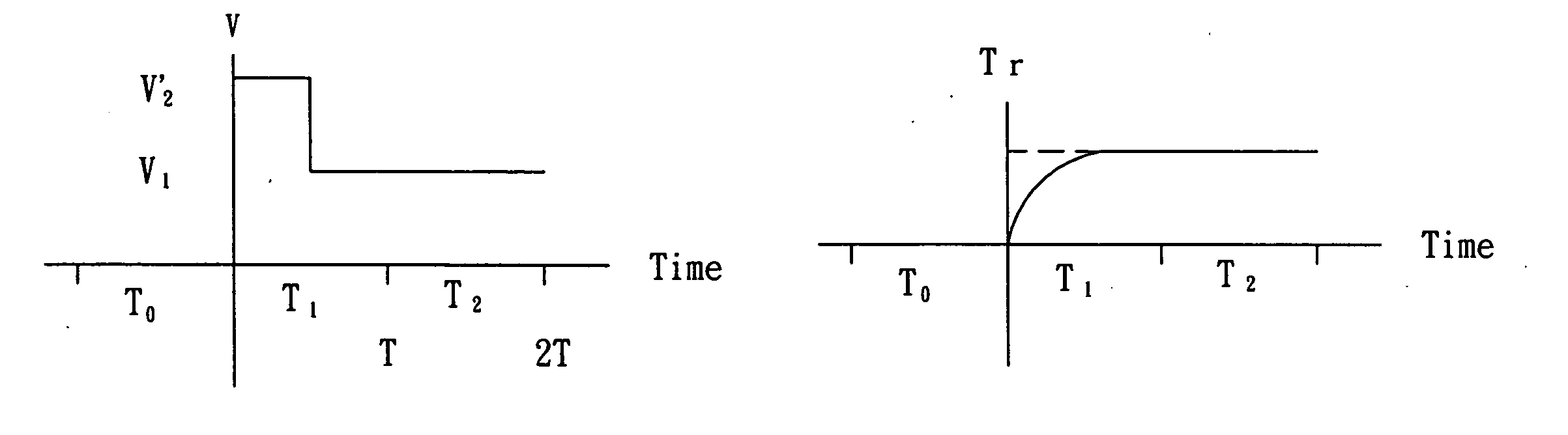
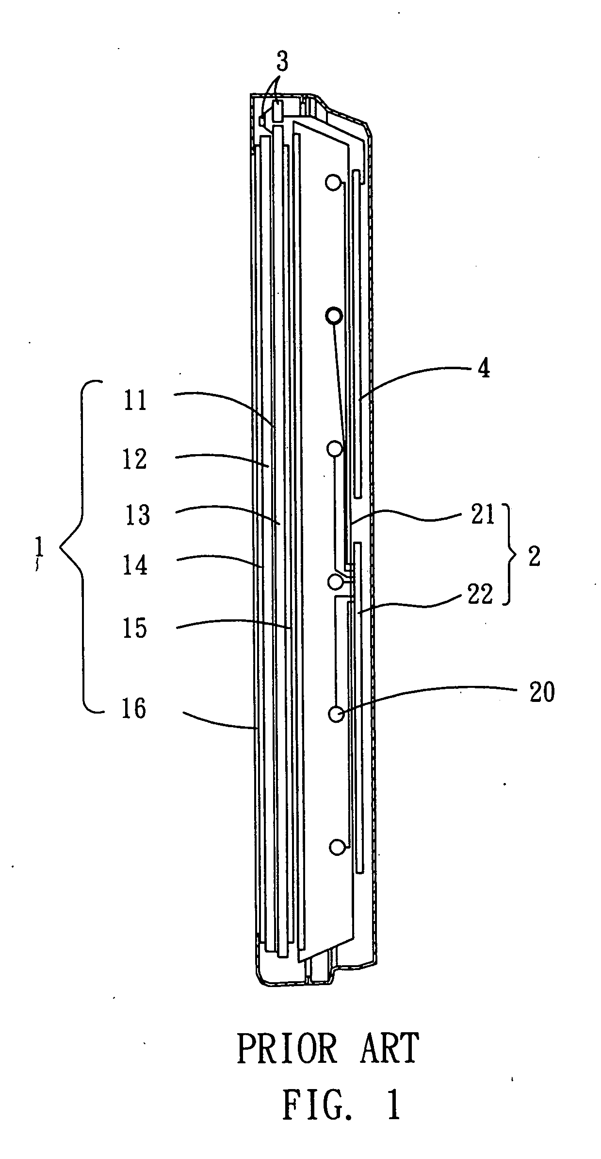
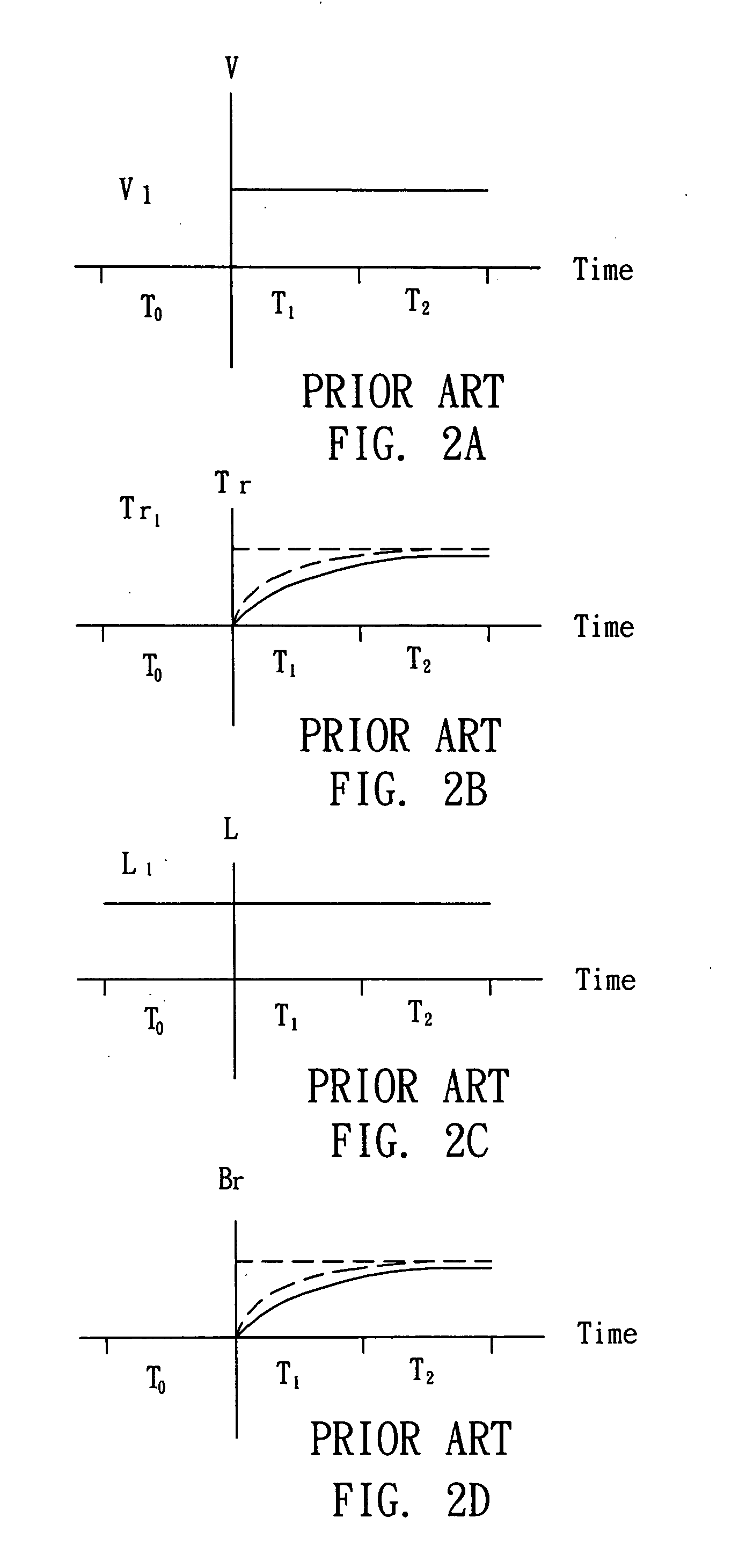
[0036] In the following embodiment, the LCD can be an LCD TV or a common LCD monitor. To make the descriptions more comprehensive, the relative references of the LCD described in the related art will be used again. The LCD comprises an LCD panel 1 and a backlight module 2. The LCD panel 1 includes a plurality of pixels, which are distributed on a displaying surface 16 of the LCD panel 1. The LCD panel 1 receives plural sets of video frame data, and a light source of the backlight module 2 projects light onto the displaying surface 16 of the LCD panel 1. Moreover, the description of the following embodiment is to drive one pixel, and three continuous sets of video frame data on the pixel, for example, have the corresponding driving voltage of 0, V1 and V2.

[0037] With reference to FI...


PUM


Abstract

A video display driving method of an LCD includes the following processes. A data transforming process transforms plural sets of video frame data into a plurality of preset voltage signal sets and post-set voltage signal sets. A display driving process writes at least one preset voltage signal of a first preset voltage signal set and at least one post-set voltage signal of a first post-set voltage signal set into at least one pixel during a frame time. During a next frame time, the display driving process then writes a preset voltage signal of a second preset voltage signal set and a post-set voltage signal of a second post-set voltage signal set into the pixel. A light controlling process controls the brightness of a backlight module, so that at the location of the pixel a first average brightness and a second average brightness is produced, and the second average brightness is greater than the first average brightness.

Description

BACKGROUND OF THE INVENTION [0001] 1. Field of Invention [0002] The invention relates to a video display driving method and, in particular, to a video display driving method for eliminating the blurring phenomenon of an LCD (Liquid Crystal Display). [0003] 2. Related Art [0004] Regarding to the application fields, the LCDs are used for monitors or televisions. In fact, the structures of the LCDs used for monitors and televisions are similar, and only different in several components, circuits and the layout of some components. [0005] With reference to FIG. 1, a conventional LCD 1 includes an LCD panel 1, a backlight module 2, a driving circuit 3, and a control circuit 4. As shown in FIG. 1, the LCD panel 1 at least includes a liquid crystal layer 11, a color filter substrate 12, a transistor circuit substrate 13, and two polarizers (a polarizer 14 and a polarizer 15). The liquid crystal layer 11 is disposed between the color filter substrate 12 and the transistor circuit substrate 13...

Claims


Application Information

Patent Timeline
Patent Type & Authority Applications(United States)
IPC IPC(8): G09G3/36
CPCG09G3/3406G09G3/3648G09G2310/024G09G2340/16G09G2320/0252G09G2320/0261G09G2320/0626G09G2310/0251
Inventor LIN, FENG-LI
Owner GIGNO TECH CO LTD
Why Eureka
Try Eureka