Rechargeable battery

Active Publication Date: 2005-12-29
SAMSUNG SDI CO LTD
View PDF3 Cites 62 Cited by
  • Summary
  • Abstract
  • Description
  • Claims
  • Application Information

AI Technical Summary

Benefits of technology

[0011] The present invention provides a rechargeable battery that has an increased current collecting effic

Problems solved by technology

When the electrode assembly is integrated with the lead elements that connect the electrode assembly with the external terminals, it becomes difficult to output a voltage that is generated in each part of the electrode assembly.
This causes a potential difference between the area where the electrode assembly is welded to the lead element and the area surrounding the welding area.
This potential difference degrades the welding area and the degradation increases as the battery is charged repeatedly.
Consequently, the output of the battery drops and the lifespan of the battery shortens.
These problems are exacerbated in a battery for driving a motor

Method used


Image

  • Rechargeable battery
  • Rechargeable battery
  • Rechargeable battery

Examples


Embodiment Construction

[0024] The rechargeable battery of the present invention may be used as a high-power energy source for driving a motor which is used for hybrid electric vehicles (HEV), electric vehicles (EV), wireless appliances, motorbikes, and motor scooters which require high power performance. To achieve this, numerous rechargeable batteries are connected in series to form a battery module. In order to provide sufficient power, each rechargeable battery must have excellent current collecting efficiency.

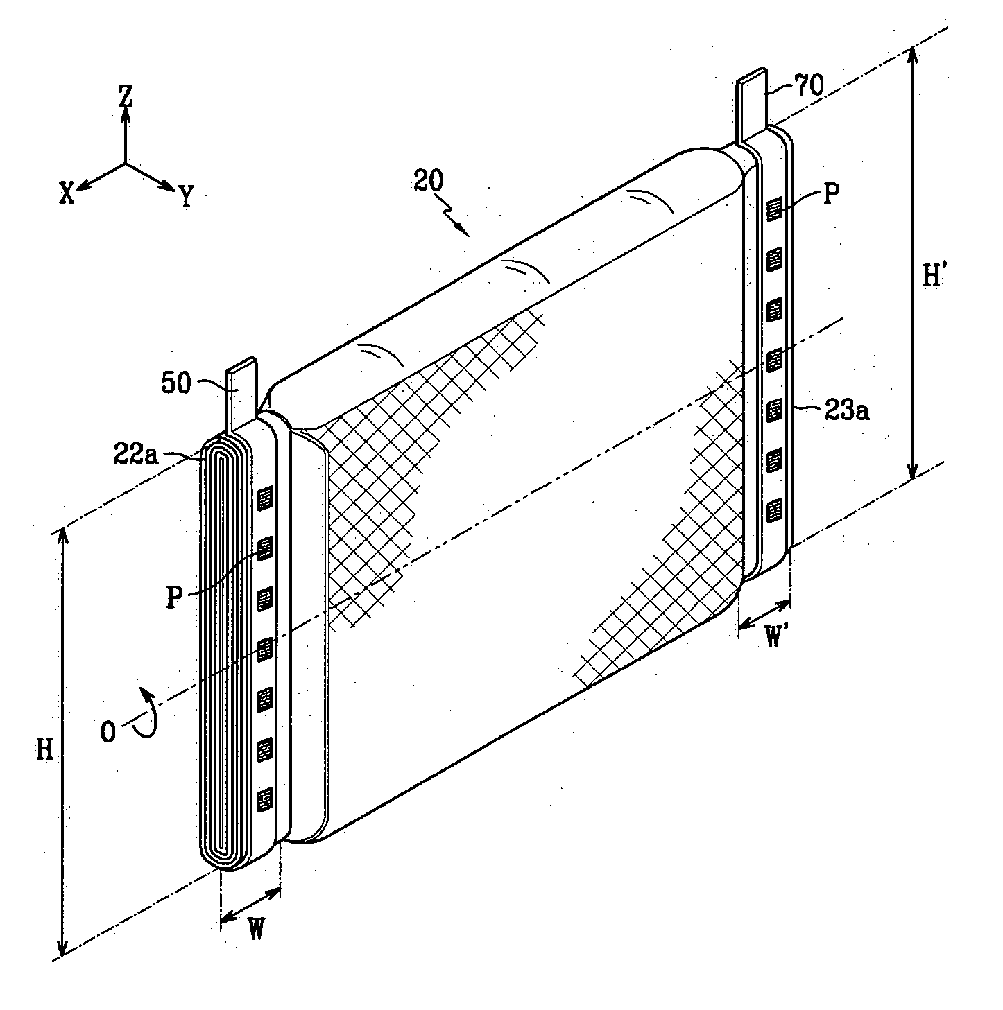
[0025] The current collecting efficiency of the rechargeable battery of the present invention may be maximized by placing the lead elements over more than a half of the periphery of the uncoated regions and thereby widening the contact area between the lead elements and the uncoated regions to reduce contact resistance.

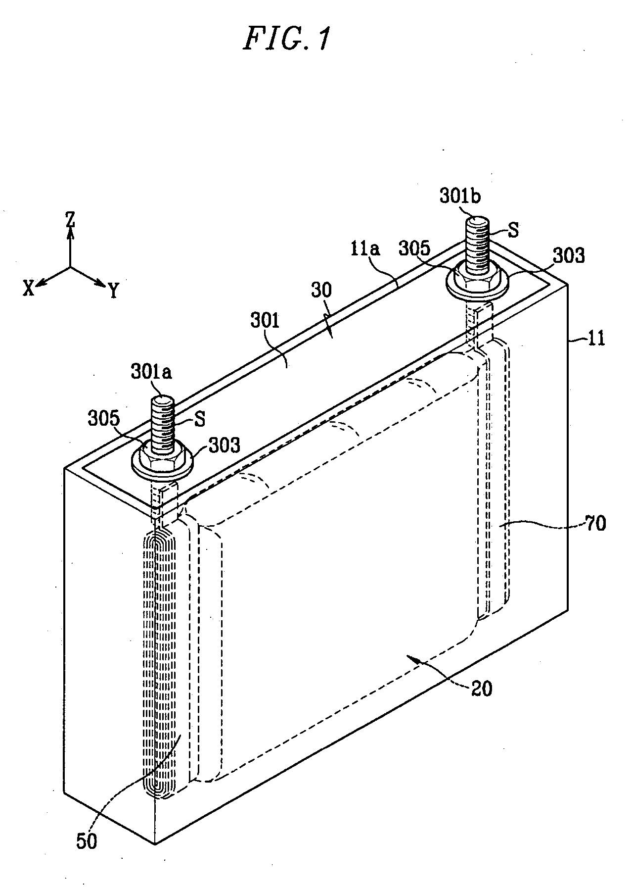
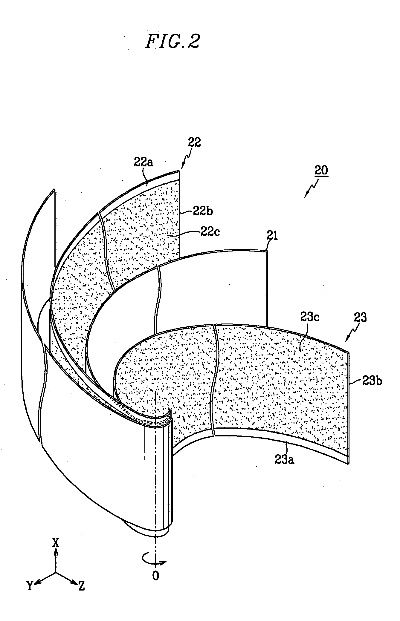
[0026]FIG. 1 is a perspective view of a rechargeable battery in accordance with an exemplary embodiment of the present invention. FIG. 2 is an exploded perspective view of an ele...


PUM


Abstract

A rechargeable battery comprises an electrode assembly including a positive electrode, a negative electrode, and a separator that is interposed between the positive electrode and negative electrode. The battery further comprises a case for housing the electrode assembly, a cap assembly for sealing the case, a positive terminal and a negative terminal placed in the cap assembly and coupled with the electrode assembly, and lead elements that are coupled with the electrode assembly and the positive terminal and negative terminal. The positive and negative electrodes include uncoated regions that are not coated with positive active materials or negative active materials, respectively, and the lead elements are placed along the periphery of the uncoated regions to be coupled with at least half of the uncoated regions.

Description

CROSS REFERENCE TO RELATED APPLICATION [0001] This application claims priority to and the benefit of Korean patent application No. 10-2004-0047014, filed in the Korean Intellectual Property Office on Jun. 23, 2004, the entire disclosure of which is incorporated herein by reference. BACKGROUND OF THE INVENTION [0002] 1. Field of the Invention [0003] The present invention relates to a rechargeable battery. More particularly, it relates to a structure connecting an electrode assembly with lead elements. [0004] 2. Discussion of the Background [0005] A rechargeable battery may be charged and discharged unlike a nonrechargeable battery that may not be recharged. A low capacity rechargeable battery that comprises a pack shaped battery cell may be used as a power source for various small portable electronic devices such as cellular phones, laptop computers, and camcorders. A high capacity rechargeable battery that has several tens of the battery cells that are connected may be used as power...

Claims


Application Information

Patent Timeline
IPC IPC(8): H01M4/70H01M50/541H01M10/04H01M50/571H01M50/176H01M50/528H01M50/536H01M50/55H01M50/553
CPCH01M2/06H01M2/22H01M10/0431H01M2/30H01M4/70H01M2/26Y02E60/10H01M50/528Y02P70/50H01M50/55H01M50/553H01M50/536H01M50/176H01M50/571H01M50/20
Inventor CHO, KYU-WOONG
Owner SAMSUNG SDI CO LTD
Why Eureka
Try Eureka