Automatic gain control for satellite digital audio radio service receiver, method of automatically controlling gain and SDARS receiver incorporating the same

a satellite digital audio radio and receiver technology, applied in the direction of gain control, digital transmission, transmission monitoring, etc., can solve the problems of unnecessarily interrupted subscriber service, more difficult processing of remaining receivers, and increased noise interference, so as to reduce noise interference, increase the perceived power of satellite signals, and improve receiver performance

Active Publication Date: 2005-12-29
LUCENT TECH INC
View PDF8 Cites 3 Cited by
  • Summary
  • Abstract
  • Description
  • Claims
  • Application Information

AI Technical Summary

Benefits of technology

[0011] Those skilled in the pertinent art have long understood that filters can be used to reduce the noise interference creates in a received signal, including those received from satellites. However, the present invention recognizes that interference can degrade receiver performance in another, more subtle way: the noise or distortion increases the perceived power of the received satellite signal. SDARS receivers use automatic gain control (AGC) based on the power of the received satellite signal to control the initial amplification of the received satellite signal. When a conventional SDARS AGC falsely perceives the received satellite's signal to be stronger than it really is, the AGC responds by calling for less amplification of the signal. Consequently, the remainder of the receiver has a more difficult time processing the underamplified signal, which, because SDARS receivers are predominantly digital, often means that the subscriber's service is temporarily completely, but unnecessarily, interrupted.
[0012] Therefore, in one aspect, the present invention provides an AGC for a SDARS receiver. In one embodiment, the AGC includes: (1) an AGC function selector configured to compare first and second time division multiplexed (TDM) power signals and a nonzero threshold and select an AGC function based thereon and (2) an AGC function applier associated with the AGC function selector and configured to apply the AGC function to the first and second TDM power signals to develop therefrom an AGC control signal.
[0013] In another aspect, the present invention provides a method of automatically controlling gain. In one embodiment, the method includes: (1)

Problems solved by technology

Consequently, the remainder of the receiver has a more difficult time processing the underamplified signal, which, because SDARS rece

Method used


Image

  • Automatic gain control for satellite digital audio radio service receiver, method of automatically controlling gain and SDARS receiver incorporating the same
  • Automatic gain control for satellite digital audio radio service receiver, method of automatically controlling gain and SDARS receiver incorporating the same
  • Automatic gain control for satellite digital audio radio service receiver, method of automatically controlling gain and SDARS receiver incorporating the same

Examples


example 1

Two AGC Functions, One Step

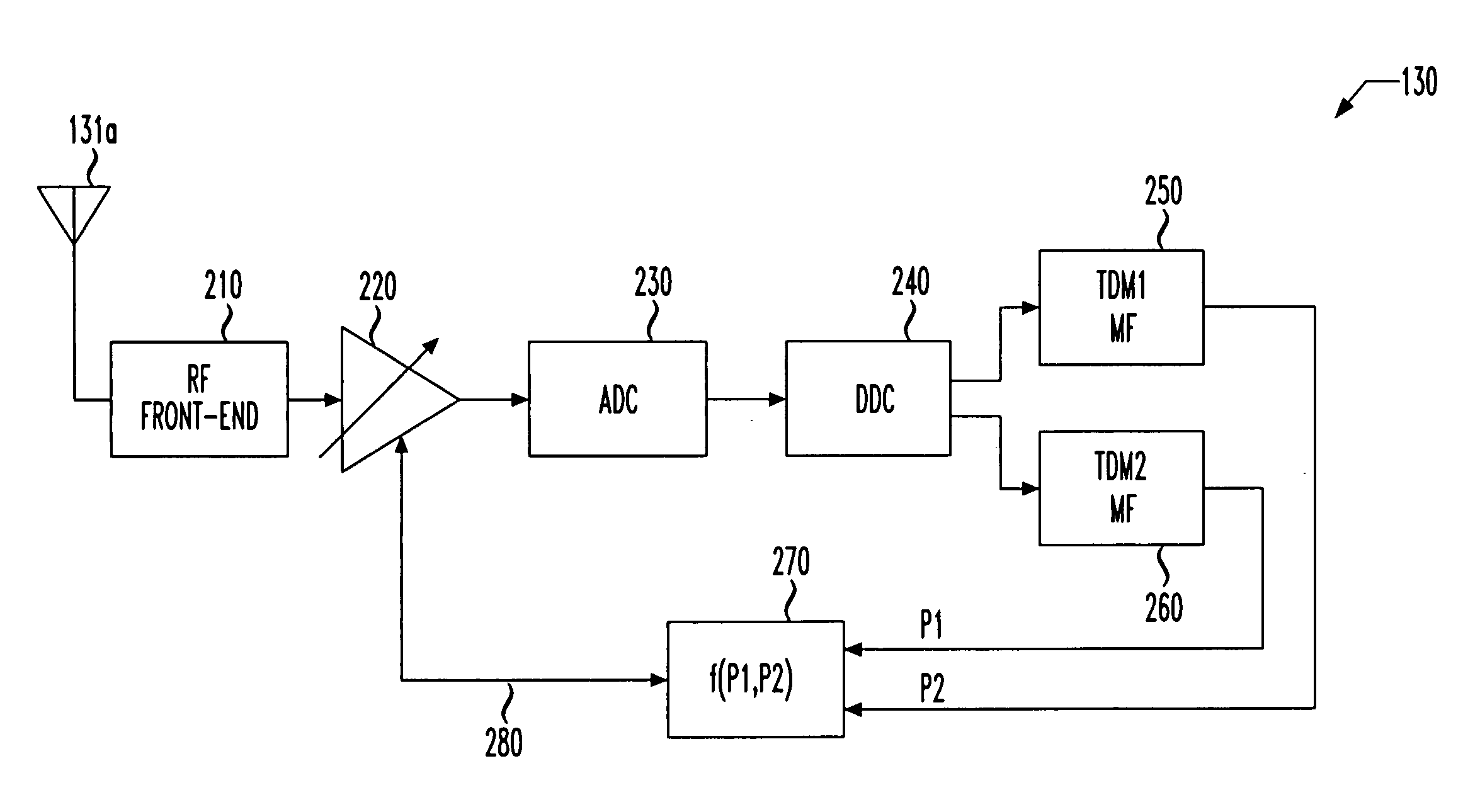
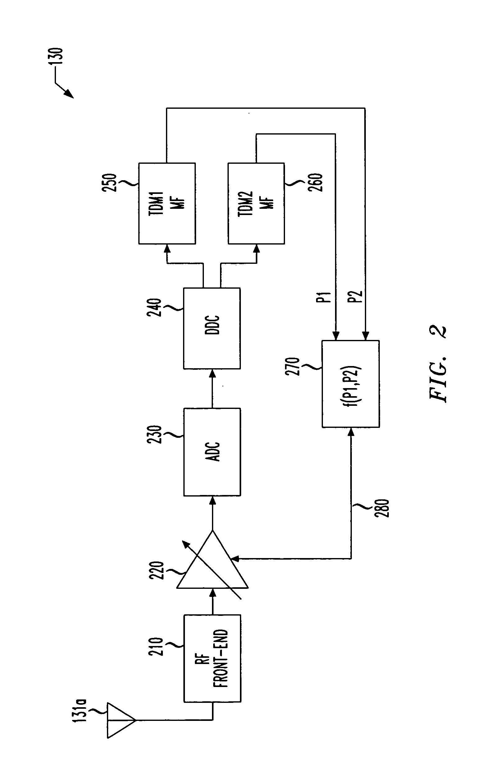
[0037] For Example 1, it will be assumed that, if P2−P11,P2) AGC function is suitable for developing the AGC control signal. However, if P2−P1>=T, another AGC function is needed. In Example 1, that AGC function is f(P1,P2)=P1 (simply the first TDM power signal). Thus, the following two AGC functions result: f(P1,P2)={max⁡(P1,P2)P2-P1<TP1P2-P1>=T.

[0038] One possible disadvantage of Example 1 is that a step exists between the f(P1,P2)=max(P1,P2) AGC function and the f(P1,P2)=P1 AGC function. The instability in the AGC control signal that results from the step may be sufficient to cause bit error rates (BER) in the SDARS receiver 130 of FIG. 1 to increase to an unacceptable level. However, the step may be acceptable in some applications.

example 2

Three AGC Functions, Two Steps

[0039] For Example 2, it will again be assumed that, if P2−P1(P1,P2)=max(P1,P2) AGC function is suitable for developing the AGC control signal. However, the f(P1,P2)=P1 AGC function will only be allowed when P2−P1>2T. In the interim region of T2−P1(P1,P2)=(P1+P2) / 2 (an average of the first and second TDM power signals). Thus, the following three AGC functions result: f(P1,P2)={max⁡(P1,P2)P2-P1<T(P1+P2) / 2T<=P2-P1<2⁢TP1P2-P1>=2⁢T.

[0040] It is apparent, however, that two steps exist between the f(P1,P2)=(P1+P2) / 2 AGC function and the f(P1,P2)=P1 AGC function. The instability in the AGC control signal that results from these two somewhat smaller steps may still be sufficient to cause BER in the SDARS receiver 130 of FIG. 1 to increase to an unacceptable level. However, the steps may be acceptable in most if not all applications.

example 3

Three AGC Functions, No Steps

[0041] For Example 3, it will again be assumed that, if P2−P1(P1,P2)=max(P1,P2) AGC function is suitable for developing the AGC control signal and also that the f(P1,P2)=P1 AGC function is suitable when P2−P1>2T. In the interim region of T2−P1(P1,P2)=2(P1+T)-P2 (a difference between twice a sum of the first TDM power signal and the nonzero threshold and the second TDM power signal). Thus, the following three AGC functions result: f(P1,P2)={max⁡(P1,P2)P2-P1<T2⁢(P1+T)-P2T<=P2-P1<2⁢TP1P2-P1>=2⁢T.

[0042] It is apparent that the steps of Examples 1 and 2 have been eliminated, which should improve the stability in the AGC control signal and the resulting BER in the SDARS receiver.

[0043] Those skilled in the pertinent art will readily see that many variations of the above examples are possible. Other multiples of the nonzero threshold may be useful to define other function domains. Multiple nonzero thresholds may be used. Many other AGC functions ...


PUM


Abstract

An automatic gain control (AGC) for a Satellite Digital Audio Radio Service (SDARS) receiver, a method of automatically controlling gain and a SDARS receiver incorporating the AGC or the method. In one embodiment, the AGC includes: (1) an AGC function selector configured to compare first and second time division multiplexed (TDM) power signals and a nonzero threshold and select an AGC function based thereon and (2) an AGC function applier associated with the AGC function selector and configured to apply the AGC function to the first and second TDM power signals to develop therefrom an AGC control signal.

Description

TECHNICAL FIELD OF THE INVENTION [0001] The present invention is directed, in general, to automatic gain control (AGC) and, more specifically, to an AGC for a Satellite Digital Audio Radio Service (SDARS) receiver, a method of automatically controlling gain and a SDARS receiver incorporating the AGC or the method. BACKGROUND OF THE INVENTION [0002] The last several decades have brought significant changes to broadcast radio technology. First came amplitude modulation (AM) analog radio, then, in turn, frequency modulation (FM) analog radio, FM-AM and FM multiplex stereo analog radio, FM discrete stereo analog radio, FM multiplex quadraphonic analog radio and, finally, AM discrete stereo analog radio. Some of these radio technologies proved longer-lasting than others. However, the latest in high-tech broadcast radio, Satellite Digital Audio Radio Service, or SDARS, is capable of providing a new level of service to the subscribing public. [0003] SDARS promises to overcome several perce...

Claims


Application Information

Patent Timeline
IPC IPC(8): H03G3/20H03G3/30H04B1/06H04B7/00H04H1/00H04H40/90H04L27/08
CPCH03G3/3052H04B7/18523H04H40/90H03G3/3078
Inventor FISHMAN, DAVID A.MALKEMES, ROBERT C.ORLANDO, DENIS P.SONG, JIEZHONG, ERICZHU, YING
Owner LUCENT TECH INC
Why Eureka
Try Eureka