Pneumatically actuated drain stopper system and apparatus

a technology of pneumatic actuator and stopper, which is applied in the field of plumbing fixtures, can solve the problems of less-than-ideal drain stopper control device, less-than-ideal drain stopper, and insufficient rise of the stopper from the drain to enable the evacuation of the contained waste water of the basin, etc., and achieves the effect of smooth and reliable operation

Inactive Publication Date: 2006-01-05
THE WESTBRASS
View PDF9 Cites 34 Cited by
  • Summary
  • Abstract
  • Description
  • Claims
  • Application Information

AI Technical Summary

Benefits of technology

[0011] It is yet another object of the present invention to provide a stopper device system which operates s

Problems solved by technology

The physical and functional elements comprising the typical sink include several intersecting sharp abrasive surfaces that are not shielded and which, over time, loosen and become mechanically compromised.
They then present to a user a less-than-ideal drain stopper control device.
Over time, the typical pop-up linkage can become so loose that when the control rod is pushed or pulled to its fully usable length, the stopper may not rise from the drain sufficiently to enable its basin to be evacuated of its contained waste water in a reasonably short period of time; additionally, it will not sufficiently seat upon the drain inlet to provide a substantially water-tight seal to retain water within the basin.
Moreover, wearing of the parts, corrosion, friction at

Method used


Image

  • Pneumatically actuated drain stopper system and apparatus
  • Pneumatically actuated drain stopper system and apparatus
  • Pneumatically actuated drain stopper system and apparatus

Examples


embodiment 300

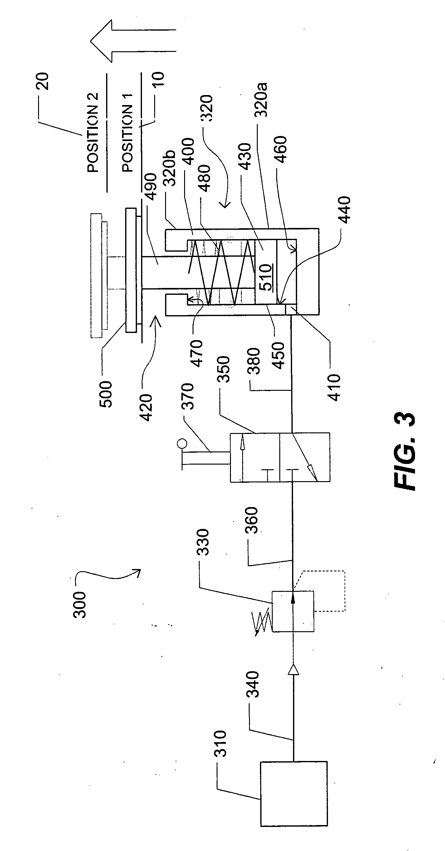
[0038] Referring now to FIG. 3, which is a schematic view of a second preferred embodiment 300 of a pneumatic apparatus for actuating movement of a drain stopper, it is seen that the inventive apparatus comprises, in its most essential aspect, a gas source 310 in fluid communication with a piston drain 320. The gas source may be one or more portable compressed gas cylinders or a compressor apparatus including a motor and gas storage tanks. The piston drain includes a lower portion 320a and an upper portion 320b. Interposed between the gas source and piston drain are devices for controlling and regulating the translation of pressurized gas from the gas source to the piston drain, including: a pneumatic pressure regulator 330, either integral with the gas source or connected to it with a pneumatic line 340; a switch 350, either integral with the pressure regulator or in fluid communication with the pressure regulator through a pneumatic line 360, and which includes a toggle element or...

embodiment 600

[0042] Referring now to FIG. 4, in a third preferred embodiment 600 of the present invention, the apparatus is adapted for use in selectively operating the flapper assembly in a toilet flush mechanism. Accordingly, the piston head includes a small gas exit port 610, which is not under the control of a switch and which is dimensioned to permit a slow flow of air to pass during operation of the mechanism. As gas passes into the pneumatic housing 620, a small portion of gas is also allowed to pass through exit port 610, but not so much as to undermine the force effecting the elevation of the piston 630. However, gas continues to pass through exit port even after the piston has been pushed into the raised position, until the force of the compressed gas beneath the piston and urging it upwardly is surpassed by the force of the compression spring urging the piston downwardly. Accordingly, the apparatus will not allow water to be wasted in a continual flush. Other elements in this third pr...

embodiment 700

[0043]FIG. 5 shows a fourth preferred embodiment 700 of the present invention, again comprising as essential elements a gas source 710, a pressure regulator 720, a three-port switch 730 having a push button 740, a piston drain 750, and connecting pneumatic lines as needed. In this embodiment, however, the pneumatic housing 760 of the piston drain has a gas inlet 770 disposed in the upper portion 760a of the housing and a compression spring 780 disposed between the piston head 790 of the piston 800 and the floor 810 of the pneumatic housing. A seal 820 is disposed in the opening 830 in the upper portion 760a of the housing and around the connecting rod 840 of the piston to prevent pressure loss. In this instance, when the push button 740 is depressed, compressed gas enters the pneumatic housing and drives the piston down, thus lowering the drain stopper 850. When the push button is again depressed, the pressure is released by the switch and the compression spring urges the piston hea...


PUM


Abstract

A pneumatically actuated drain stopper system and apparatus which includes a source of compressed gas, a pressure regulator, a piston drain, a push-button or toggle switch interposed between the piston drain and the pressure regulator, and pneumatic lines connecting the piston drain to the switch and the switch to the gas source, and bringing all elements into fluid communication with one another.

Description

CROSS REFERENCE TO RELATED APPLICATIONS [0001] The present application claims the benefit of the filing date of U.S. Utility patent application Ser. No. 09 / 888,186, filed Jun. 21, 2001 (Jun. 21, 2001); and U.S. Provisional Patent Application Ser. Nos. 60 / 665,615, and 60 / 665,610, each filed Mar. 24, 2005 (Mar. 24, 2005). Each of the foregoing patent applications are incorporated in their entirety by reference herein.STATEMENT REGARDING FEDERALLY SPONSORED RESEARCH OR DEVELOPMENT [0002] Not applicable. REFERENCE TO A MICROFICHE APPENDIX [0003] Not applicable. TECHNICAL FIELD [0004] The present invention relates generally to plumbing fixtures, more particularly to a pneumatically actuated drain stopper apparatus for basins, tubs, sinks, and toilets. BACKGROUND INFORMATION AND DISCUSSION OF RELATED ART [0005] The typical modern sink, tub, or water basin employs a pop-up linkage for controlling the stopper that blocks its drain. Most commonly the pop-up linkage is purely mechanical and c...

Claims


Application Information

Patent Timeline
IPC IPC(8): E03C1/23
CPCE03C2001/2313E03C1/23
Inventor DUNCAN, SCOTT
Owner THE WESTBRASS
Why Eureka
Try Eureka