

Apparatus for generating freshwater
- Summary
- Abstract
- Description
- Claims
- Application Information
AI Technical Summary
Benefits of technology
Problems solved by technology
Method used
Image


Examples
Embodiment Construction
[0019] Exemplary embodiments of an apparatus for generating freshwater according to the present invention will be explained below in detail with reference to the accompanying drawings. It should be noted that that the invention is not limited thereto. Furthermore, constituent elements in the embodiments below include elements that persons skilled in the art can easily assume or that are substantially the same.
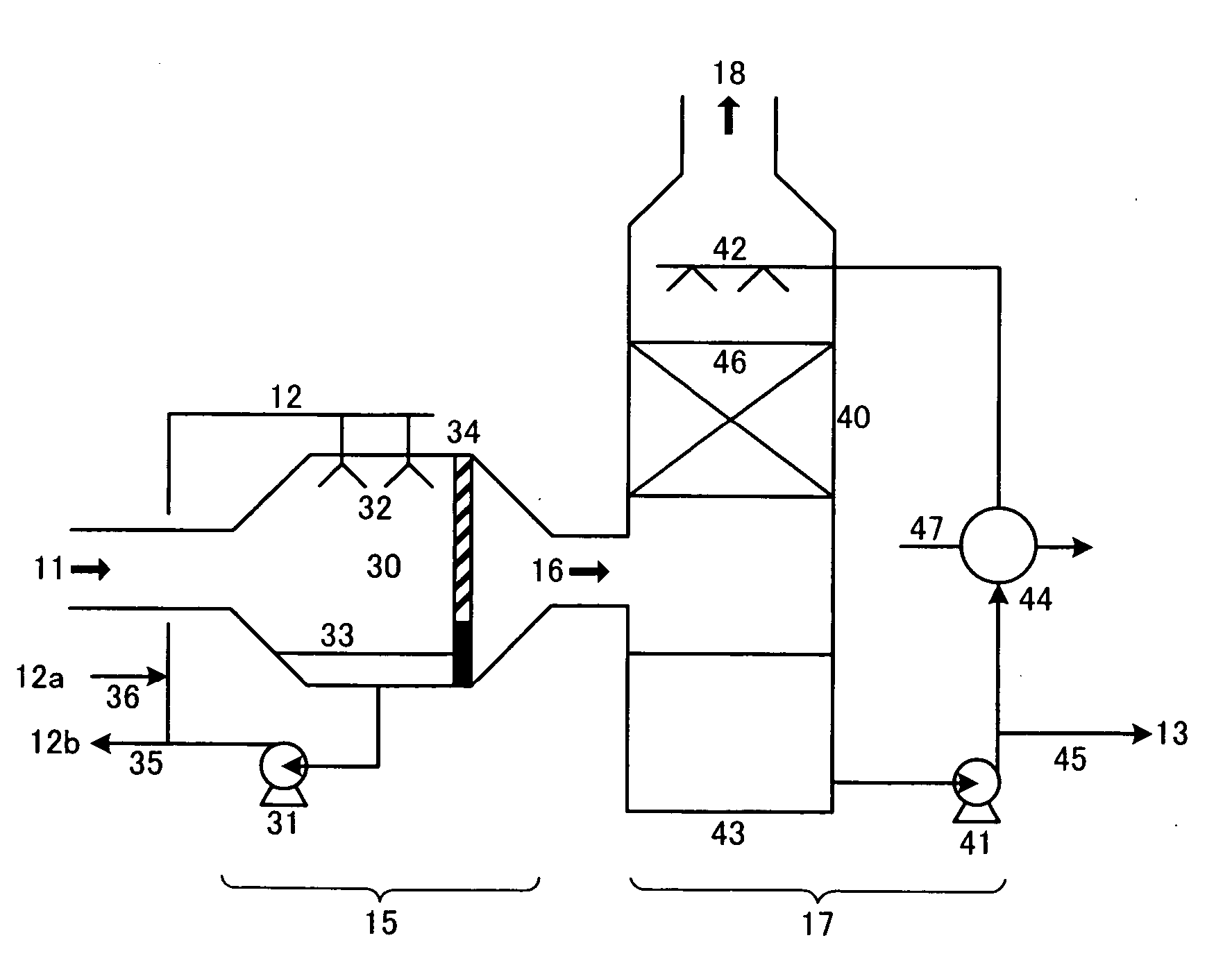
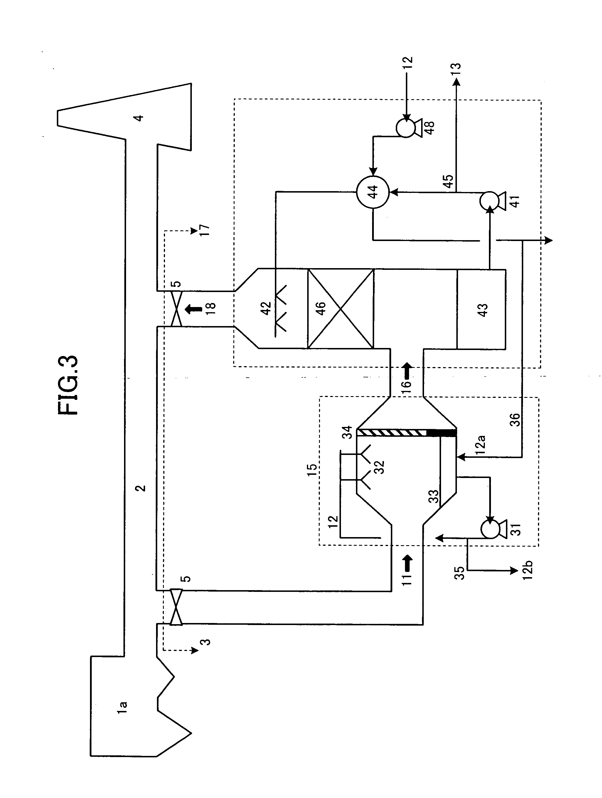
[0020]FIG. 1 is a conceptual view of the freshwater generating apparatus according to the first embodiment of the present invention. The freshwater generating apparatus 3 is an apparatus for generating freshwater 13 using an exhaust combustion gas 11 from a burning unit 1 and seawater 12. The freshwater generating apparatus 3 includes a water spraying unit 15 that sprays the seawater 12 into the exhaust combustion gas 11 and a freshwater collecting unit 17 that cools an exhaust combustion gas 16 into which the seawater is sprayed.
[0021] The exhaust combustion gas 11 used in t...
PUM
| Property | Measurement | Unit |
|---|---|---|
| Combustion | aaaaa | aaaaa |
Abstract
Description
Claims
Application Information