Reaction force control apparatus

Active Publication Date: 2006-01-05
HONDA MOTOR CO LTD
View PDF2 Cites 18 Cited by
  • Summary
  • Abstract
  • Description
  • Claims
  • Application Information

AI Technical Summary

Benefits of technology

[0010] In view of the above circumstances, an object of the present invention is to provide a reaction force control apparatus by which a steering operatio

Problems solved by technology

However, when the reaction force is controlled in the aforementioned manner, the reaction force is controlled to be great due to a high yaw rate during a driving state in which steering operation torque is large, e.g., during a turning state with a high lateral acceleration.
As a resul

Method used


Image

  • Reaction force control apparatus
  • Reaction force control apparatus
  • Reaction force control apparatus

Examples


Embodiment Construction

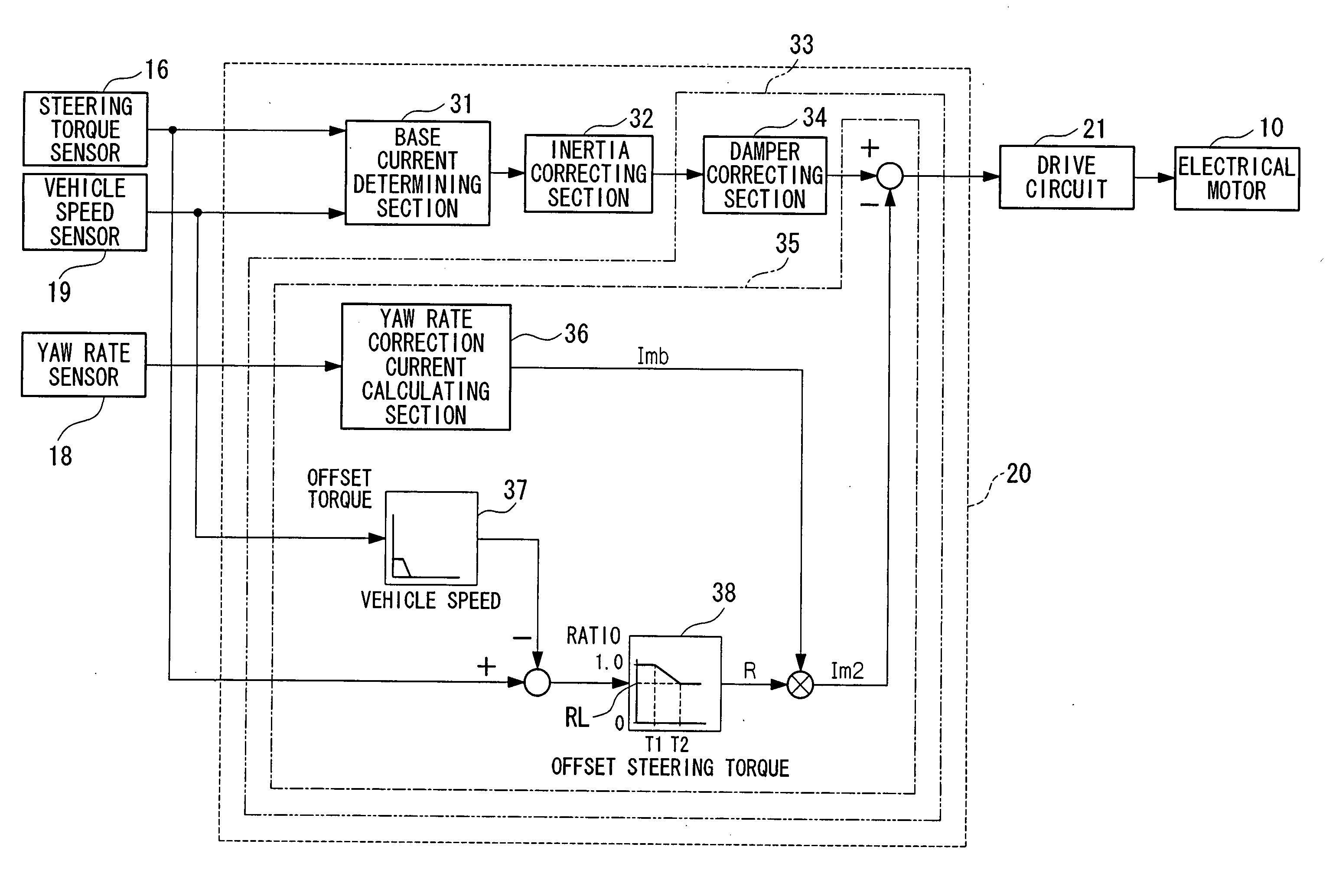
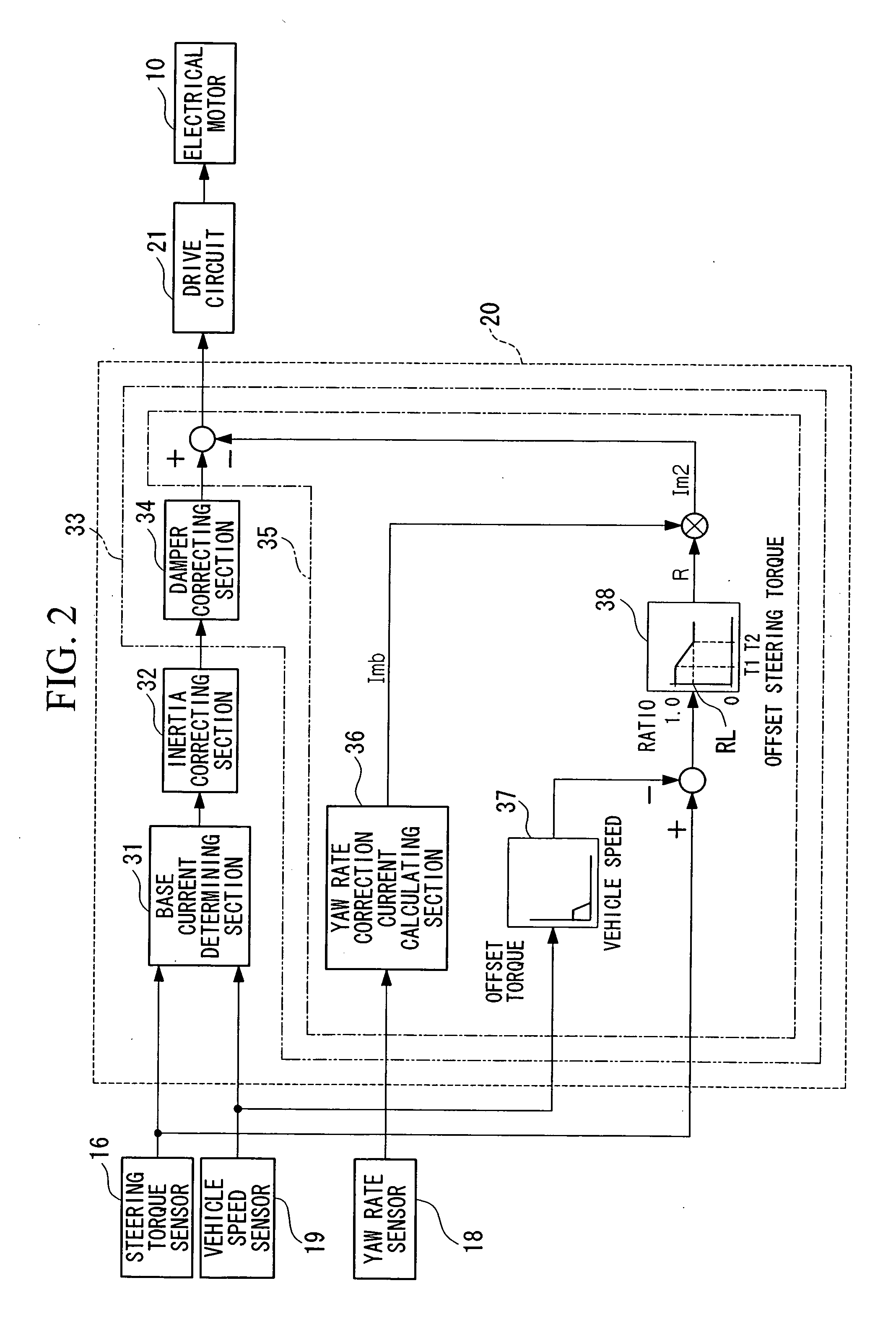
[0030] A first embodiment of a reaction force control apparatus of the present invention will be explained below with reference to FIGS. 1 to 3B. In the following first embodiment, an aspect of the present invention, which is employed in an electrical power steering apparatus, is explained.

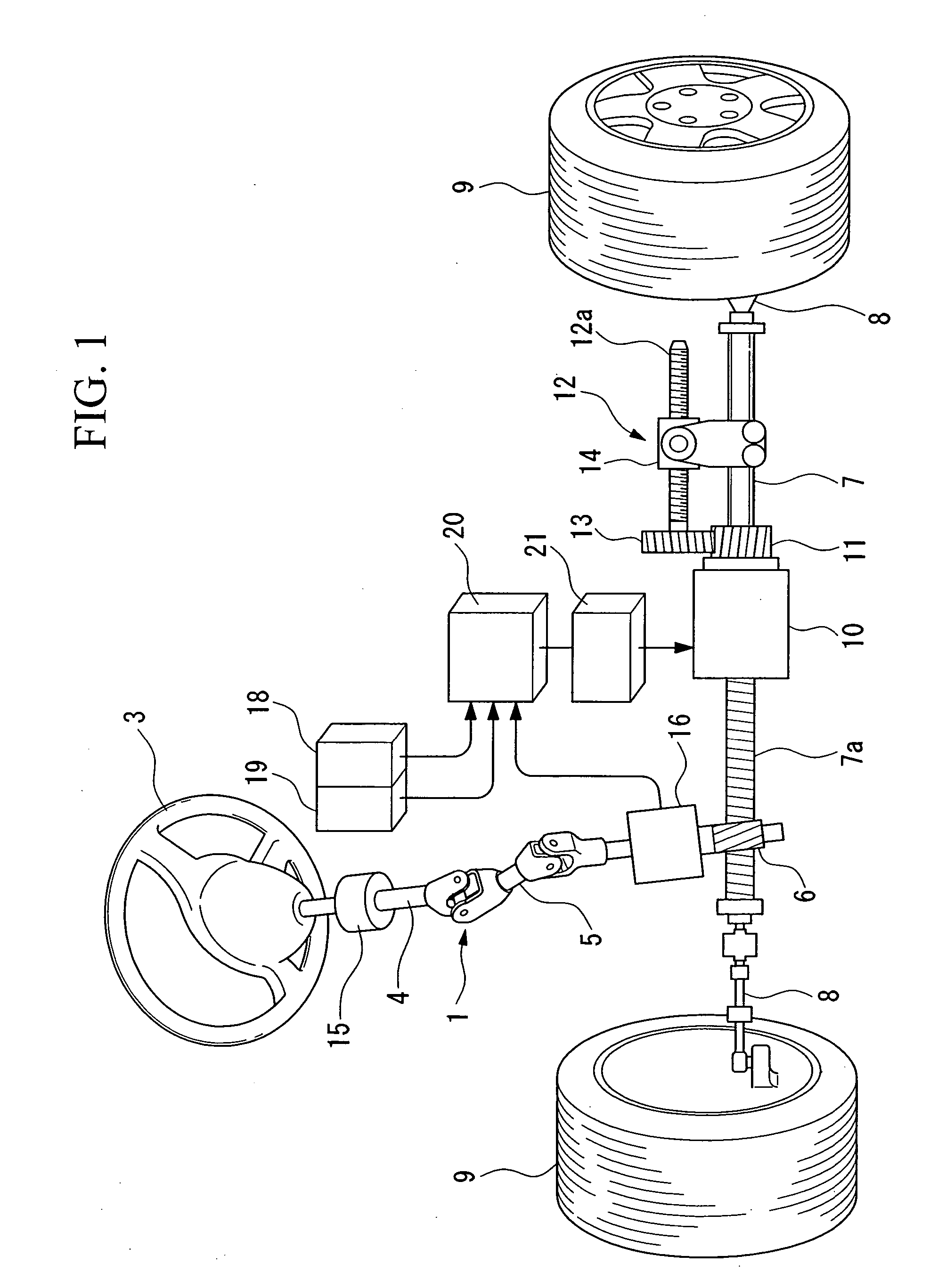
[0031] First, the construction of the electrical power steering apparatus will be explained below with reference to FIG. 1. The electrical power steering apparatus includes a manual steering force generating mechanism 1. The manual steering force generating mechanism 1 includes a steering wheel 3 (operation unit), a steering shaft 4 that is integrally connected to the steering wheel 3 and is connected to a pinion 6 of a rack and pinion mechanism via a connecting shaft having a universal joint. The pinion 6 engages a rack 7a of a rack shaft 7 that is allowed to reciprocate in a widthwise direction of the vehicle. Front wheels 9 as steerable wheels are respectively connected to the ends of the rack...


PUM


Abstract

A reaction force control apparatus for controlling a reaction force to be applied to an operation unit operated by a driver of a vehicle, the reaction force control apparatus includes a steering operation torque measuring unit for measuring steering operation torque applied to the operation unit, a vehicle movement measuring unit for measuring movement of the vehicle, and a reaction force control unit setting the reaction force to be greater as a measured value measured by the vehicle movement measuring unit is greater, and setting the reaction force to be smaller as a measured value measured by the steering operation torque measuring unit is greater.

Description

BACKGROUND OF THE INVENTION [0001] 1. Field of the Invention [0002] The present invention relates to a reaction force control apparatus for controlling reaction force to be applied to an operation unit in a steering system of a vehicle. [0003] Priority is claimed on Japanese Patent Applications No. 2004-193011 and No. 2004-193013, filed Jun. 30, 2004, the contents of which are incorporated herein by reference. [0004] 2. Description of the Related Art [0005] An electrical power steering apparatus is known as a steering apparatus for a vehicle. In an electrical power steering apparatus, a steering shaft connected to a steering wheel and a turning mechanism for turning steerable wheels are mechanically connected, and an electrical motor for assisting steering force is associated with the turning mechanism. In general, a driving torque command (drive current) for the electrical motor is controlled so that an assisting steering force is increased as the steering operation torque applied ...

Claims


Application Information

Patent Timeline
IPC IPC(8): B62D5/06
CPCB62D6/008
Inventor TAKIMOTO, SHIGENORINAKAJO, KOJIYUDA, MASATO
Owner HONDA MOTOR CO LTD
Why Eureka
Try Eureka