
Piezoresistance type accelerometer with high g values
An accelerometer and piezoresistive technology, which is applied in the field of piezoresistive high-g value accelerometers, can solve the problems of high natural frequency and high sensitivity, and achieve the effect of high natural frequency, high sensitivity and good overload resistance
- Summary
- Abstract
- Description
- Claims
- Application Information
AI Technical Summary
Problems solved by technology
Method used
Image

Examples
Embodiment Construction
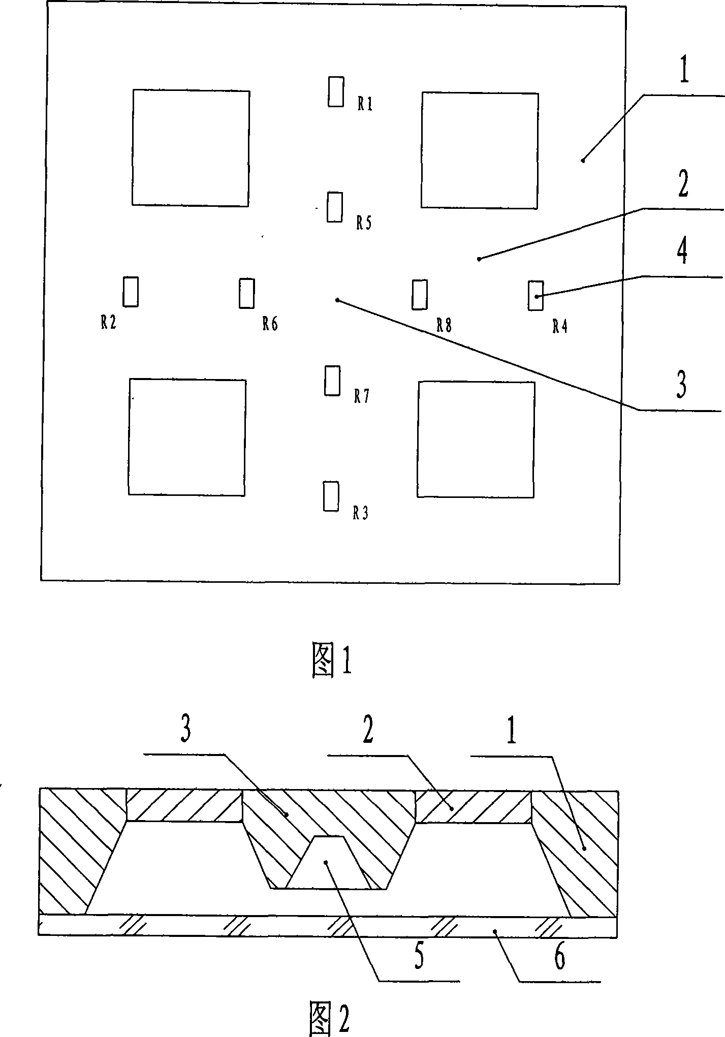
[0017] The piezoresistive high-g value accelerometer includes a silicon-based frame 1 fixed on a glass bottom plate 6, an elastic beam 2, and a mass block 3 suspended in the center of the silicon-based frame 1 through 2 elastic beams. There is a piezoresistor 4 forming a Wheatstone bridge, the beam width of the elastic beam 2 is equal to the width of the mass block 3, and the beam thickness of the elastic beam 2 is smaller than the thickness of the mass block 3, and the back of the mass block 3 has a groove 5 .
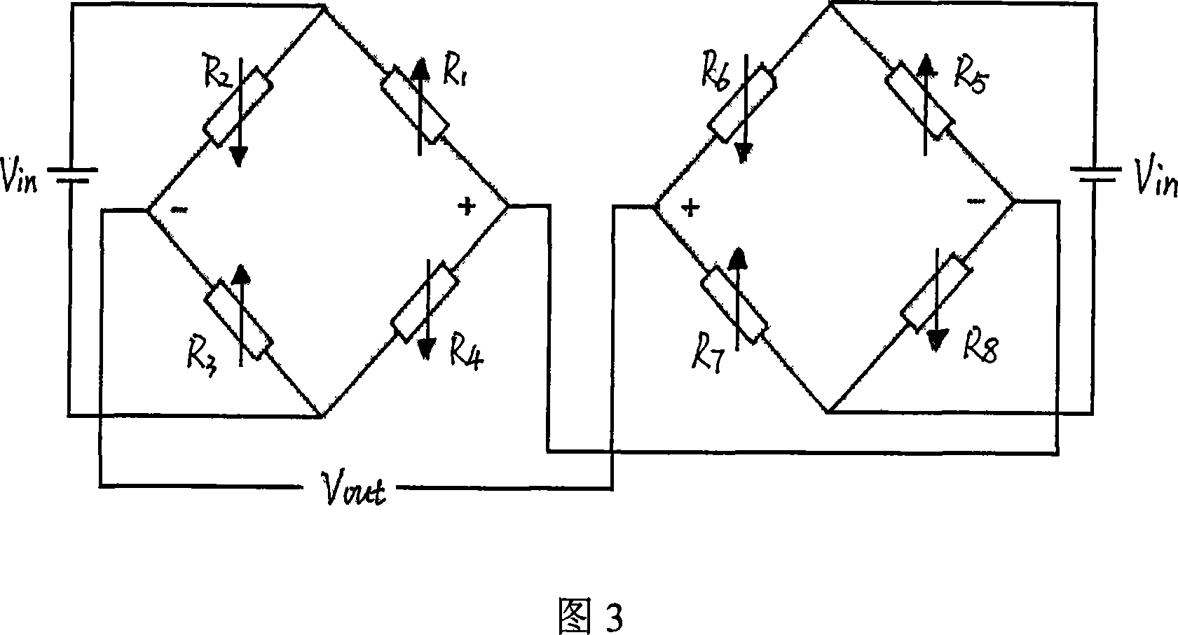
[0018] During specific implementation, piezoresistors 4 are respectively diffused at both ends of the elastic beam 2 (that is, piezoresistors 4 are arranged at the intersections of the elastic beam 2, the mass block 3, and the silicon-based frame body 1, and there are co-diffused piezoresistors on the four elastic beams. Eight piezoresistors), the piezoresistors 4 at both ends of the elastic beam 2 form two Wheatstone bridges connected in series respectively, as shown...
PUM
 Abstract
Description
Claims
Application Information