Fluid transmission device

a transmission device and fluid technology, applied in the direction of fluid couplings, gearings, interengaging clutches, etc., can solve the problems of increasing the weight of the fluid container, increasing the cost, and increasing the stress, so as to reduce the stress concentration, improve the durability of the pump shell and the transmission cover, and reduce the effect of the plate thickness

Inactive Publication Date: 2006-01-05
YUTAKA GIKEN CO LTD
View PDF4 Cites 26 Cited by
  • Summary
  • Abstract
  • Description
  • Claims
  • Application Information

AI Technical Summary

Benefits of technology

[0007] The present invention has been achieved in view of the above-mentioned circumstances, and has an object to provide a fluid transmission device in which, although the diameter of a fluid container including a pump shell and a transmission cover is increased, the durability of the pump shell and the transmission cover can be improved by alleviating excessive stress concentration on a weld between the pump shell and the transmission cover without increasing their plate thickness.

Problems solved by technology

However, when the size of the fluid container becomes large, a radial load which acts on the peripheral wall increase greatly due to an increase in centrifugal force and inner pressure, resulting in that excessive stress is likely to concentrate on a weld between the pump shell and the transmission cover.
With this arrangement, however, the weight of the fluid container greatly increases, not only increasing the cost, but also lowering performance such as acceleration response.

Method used


Image

  • Fluid transmission device
  • Fluid transmission device
  • Fluid transmission device

Examples


Embodiment Construction

[0033] A preferred embodiment of the present invention will be described below on the basis of the accompanying drawings.

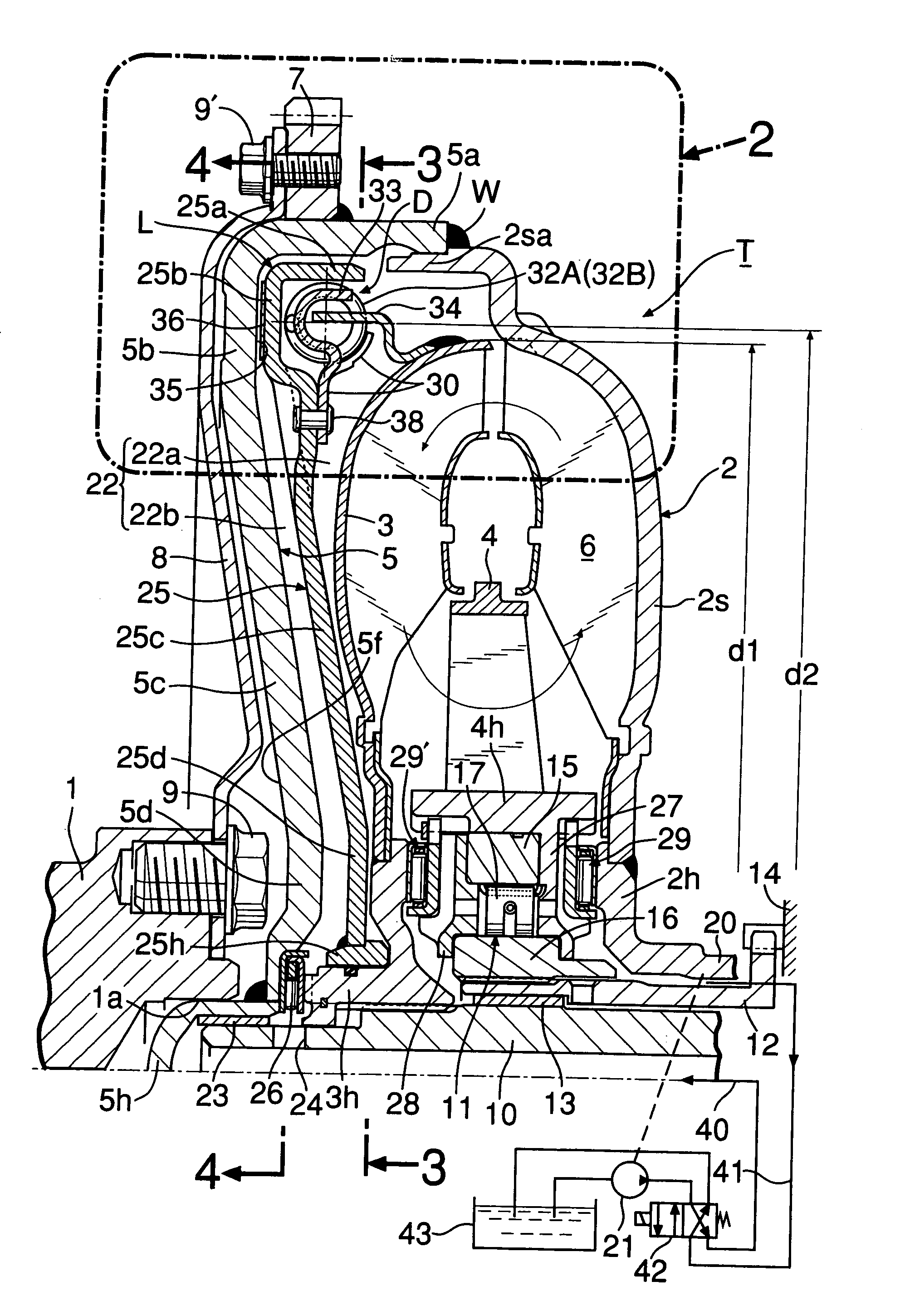
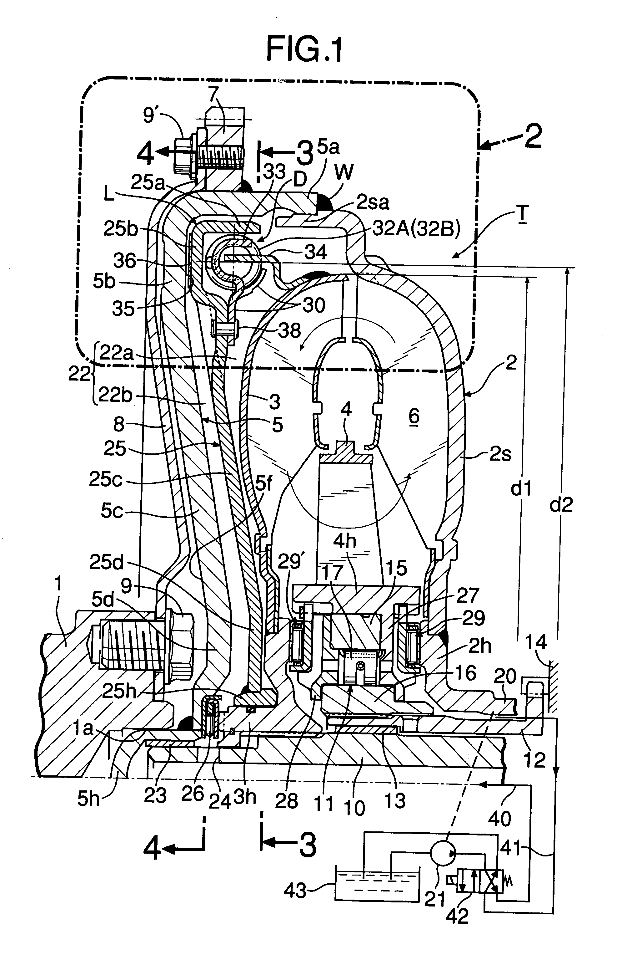
[0034] In FIG. 1, a torque converter T for automobile comprises: a pump impeller 2; a turbine impeller 3 provided to be opposed to the pump impeller; and a stator impeller 4 disposed between the inner circumferential portions of the impellers 2 and 3. A circulation circuit 6 for power transmission by a working oil is defined between these impellers 2, 3, 4. A transmission cover 5 which covers the outer surface of the turbine impeller 3 is connected to the shell of the pump impeller 2, i.e., the pump shell 2s, as follows.

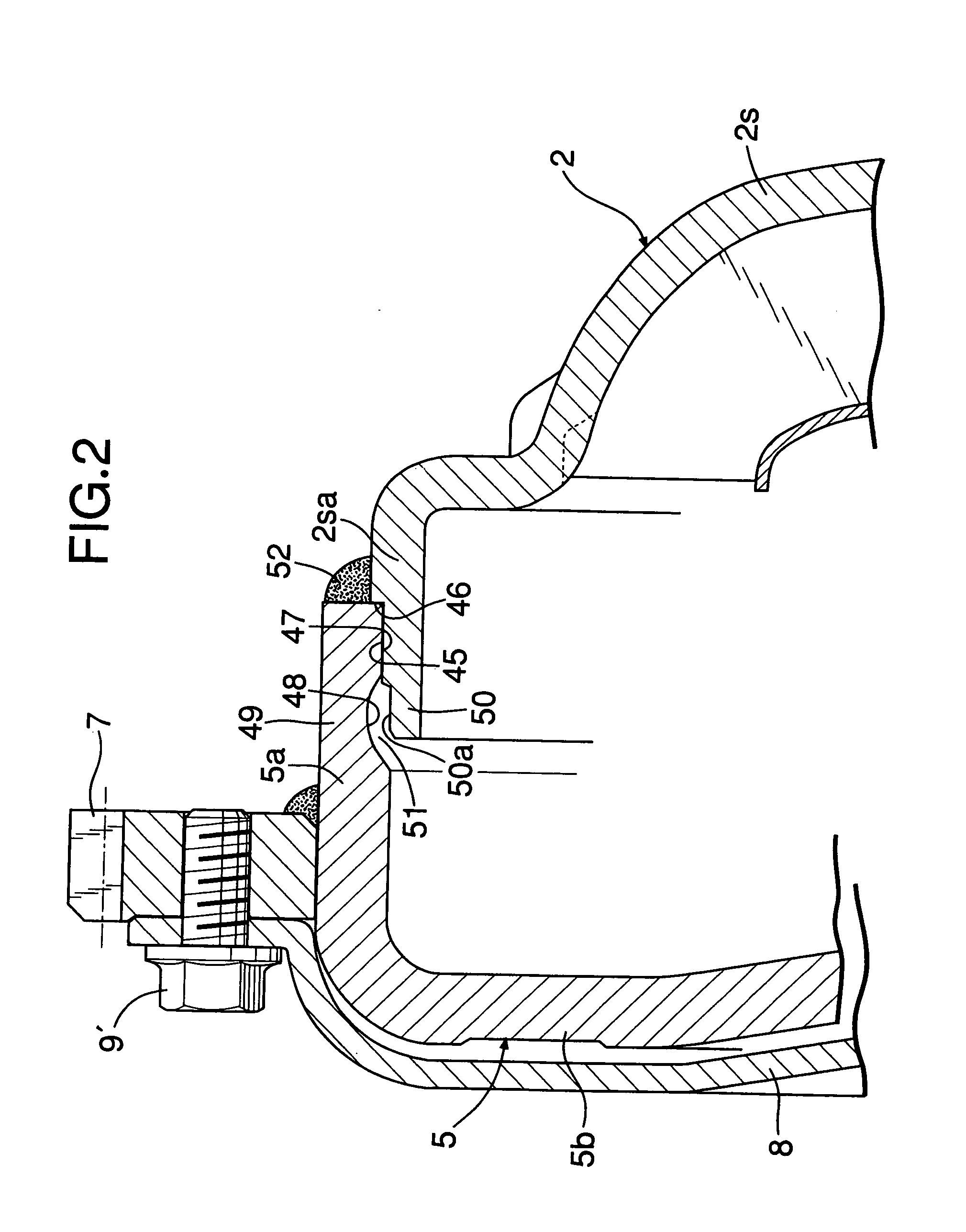
[0035] As shown in FIG. 2, the pump shell 2s integrally includes a cylindrical diameter-expanded portion 2sa which extends radially outward from the peripheral end thereof to cover the peripheral surface of the turbine impeller 3. Formed at the periphery of the diameter-expanded portion 2sa, are a male fitting surface 45 and an annular positionin...


PUM


Abstract

In a fluid transmission device, a male fitting surface of a periphery of a diameter-expanded portion of a pump shell is fitted to a female fitting surface of an inner circumference of a peripheral wall portion of a cylindrical transmission cover, and a fillet weld being is formed between an end surface of the peripheral wall portion and a peripheral surface of the diameter-expanded portion along an entire circumference, thereby connecting together the pump shell and the transmission cover. An annular recess is formed in an inner circumferential surface of the peripheral wall portion to adjoin the female fitting surface on the side opposite from the fillet weld. A portion of the transmission cover corresponding to the recess constitutes an annular thin-walled portion which has a thickness smaller than the portions of the transmission cover along the opposite sides of the annular thin wall portion. Therefore, even if the diameters of the pump shell and the transmission cover are increased, the durability of the pump shell and the transmission cover can be improved by alleviating excessive stress concentration on the fillet weld between the pump shell and the transmission cover.

Description

RELATED APPLICATION DATA [0001] The present invention is based upon Japanese priority application Nos. 2004-183319 and 2005-80200, which are hereby incorporated in their entirety herein by reference. BACKGROUND OF THE INVENTION [0002] 1. Field of the Invention [0003] The present invention relates to a fluid transmission device including a torque converter and a fluid joint which is used in an automobile and the like, and more particularly to an improvement in a fluid transmission device comprising: a turbine impeller; a pump impeller which is opposed to the turbine impeller so as to define a circulation circuit of a working oil between the pump impeller and the turbine impeller, and which has a pump shell including a diameter-expanded portion along a peripheral end portion; and a cylindrical transmission cover which defines an oil chamber in communication with the circulation circuit between the transmission cover and a back surface of the turbine impeller, a male fitting surface of...

Claims


Application Information

Patent Timeline
Patent Type & Authority Applications(United States)
IPC IPC(8): F16H41/24
CPCF16H41/28F16H2045/0294F16H2041/243F16H45/02
Inventor YAMAMOTO, YOSHIHISAYOSHIMOTO, TOKUJIKITAJIMA, AKIRA
Owner YUTAKA GIKEN CO LTD
Why Eureka
Try Eureka