Solenoid

Inactive Publication Date: 2006-01-05
SHINANO KENSHI
View PDF0 Cites 4 Cited by
  • Summary
  • Abstract
  • Description
  • Claims
  • Application Information

AI Technical Summary

Benefits of technology

[0024] In addition, since propulsion is generated at two portions that are the first yoke part and the second yoke part, even when the stroke gradually approaches zero, the region where the propulsion is stable can be widened and the control characteristics can be improved without the propulsion increasing exponentially as in the conventional art.
[0026] In addition, by assembling the first yoke part and the second yoke part with the bearing as an alignment, the respective gaps between the slider and the facing surface of the first yoke part and the facing surface of the second yoke part can be made extremely small with high precision. This means that the efficiency of the conversion from the electrical energy supplied to the excitation coil to magnetic energy is increased, and higher propulsion can be obtained.
[0027] By forming the facing surfaces on the first yoke part and the second yoke part with the same internal diameter, as described above, the efficiency of the conversion from the electrical energy supplied to the excitation coil to magnetic energy is increased, so that higher propulsion can be obtained.
[0030] With this construction, the upper end edge part of the groove is prevented from contacting and thereby damaging the bearing. This means that the working life of the solenoid can be extended.
[0031] In addition, if a recess is formed at the entrance of the bearing so that a part, which is an upper end edge part of the groove provided in the slider and is located on a far side with respect to the bearing in an axial direction, does not contact the bearing in a range where the slider moves, the upper end edge part of the groove can be prevented from contacting and thereby damaging the bearing. This means that the working life of the solenoid can be extended.

Problems solved by technology

However, when the movable range of the slider and the controlled range (the operation range) have the relationship shown in FIG. 7, it is not possible to use large propulsion within the controlled range through which control of the solenoid is actually desired.
The propulsion characteristics are also nonlinear, which means the controllability is poor.
In this kind of conventional solenoid, propulsion is generated between end surfaces of the slider at the end of the movable range and the fixed iron core part, and there has been the problem that as the movable range becomes wider, it has not been possible to set the controlled range at the optimal range in the propulsion characteristics of the solenoid.
There has also been the problem that in cases where the movable range is wide and the required propulsion in the controlled range is large, the size of the solenoid itself has to be increased to produce the propulsion.

Method used


Image

  • Solenoid
  • Solenoid
  • Solenoid

Examples


first embodiment

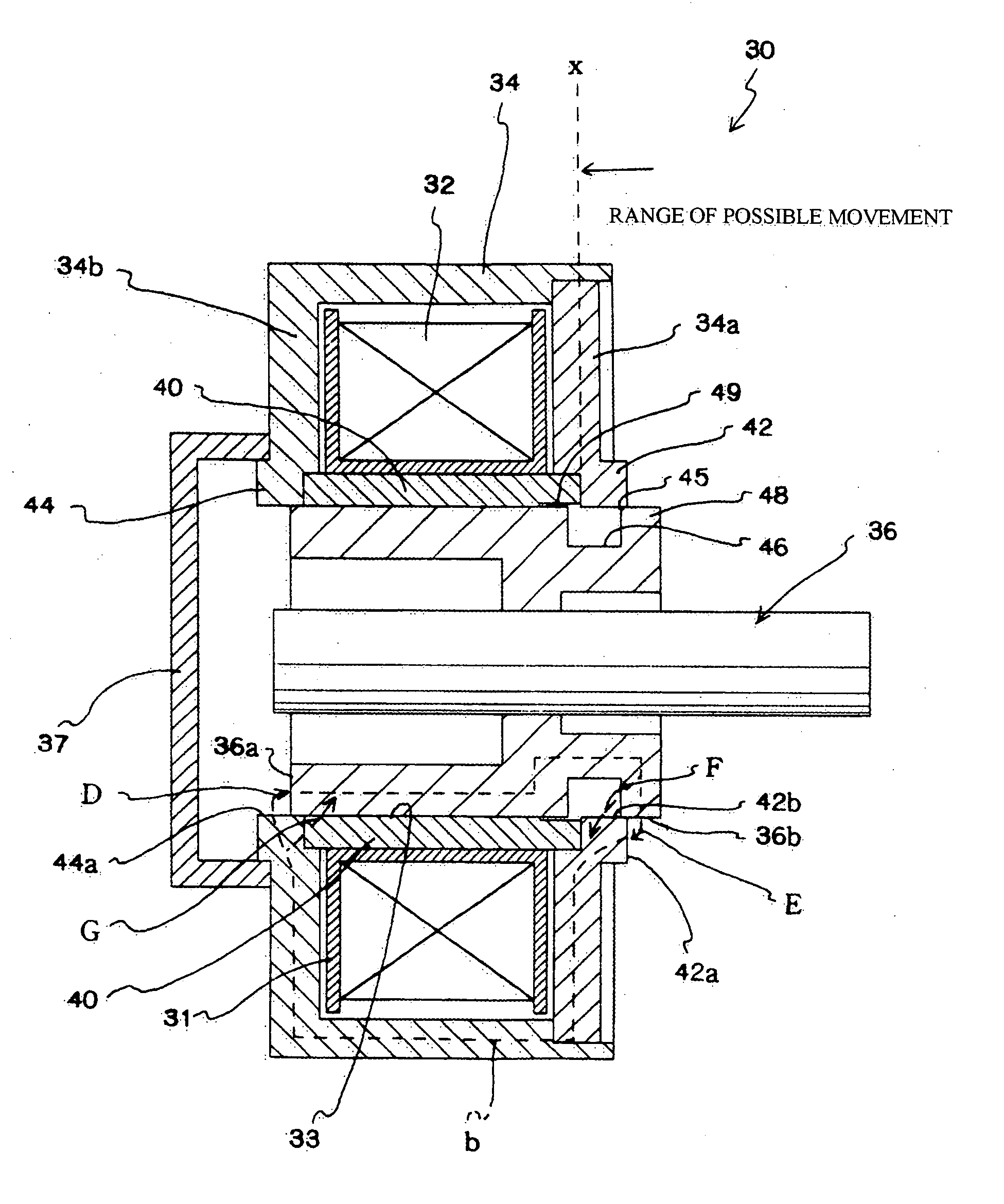
[0040] In the present embodiment, the parameters n, m given in the patent claims are set so that n=0 and m=0. The present embodiment will be described with reference to FIG. 1.

[0041] A solenoid 30 includes an excitation coil 32, a yoke 34, and a slider 36.

[0042] The excitation coil 32 is formed in a tube shape by winding a coil around a bobbin 31. An enclosure 33 in which a slider 36 can be enclosed is formed at the center of the tube-shaped excitation coil 32.

[0043] The yoke 34 is made of a magnetic material, and is formed so as to cover a periphery of the excitation coil 32. The yoke 34 is composed of an upper yoke 34a disposed at one end of the excitation coil 32 and a lower yoke 34b disposed at the other end.

[0044] It should be noted that the “first yoke part” referred to in the patent claims corresponds to the upper yoke 34a and the “second yoke part” to the lower yoke 34b. It should be noted that the “linking part” referred to in the patent claims also corresponds to the l...

second embodiment

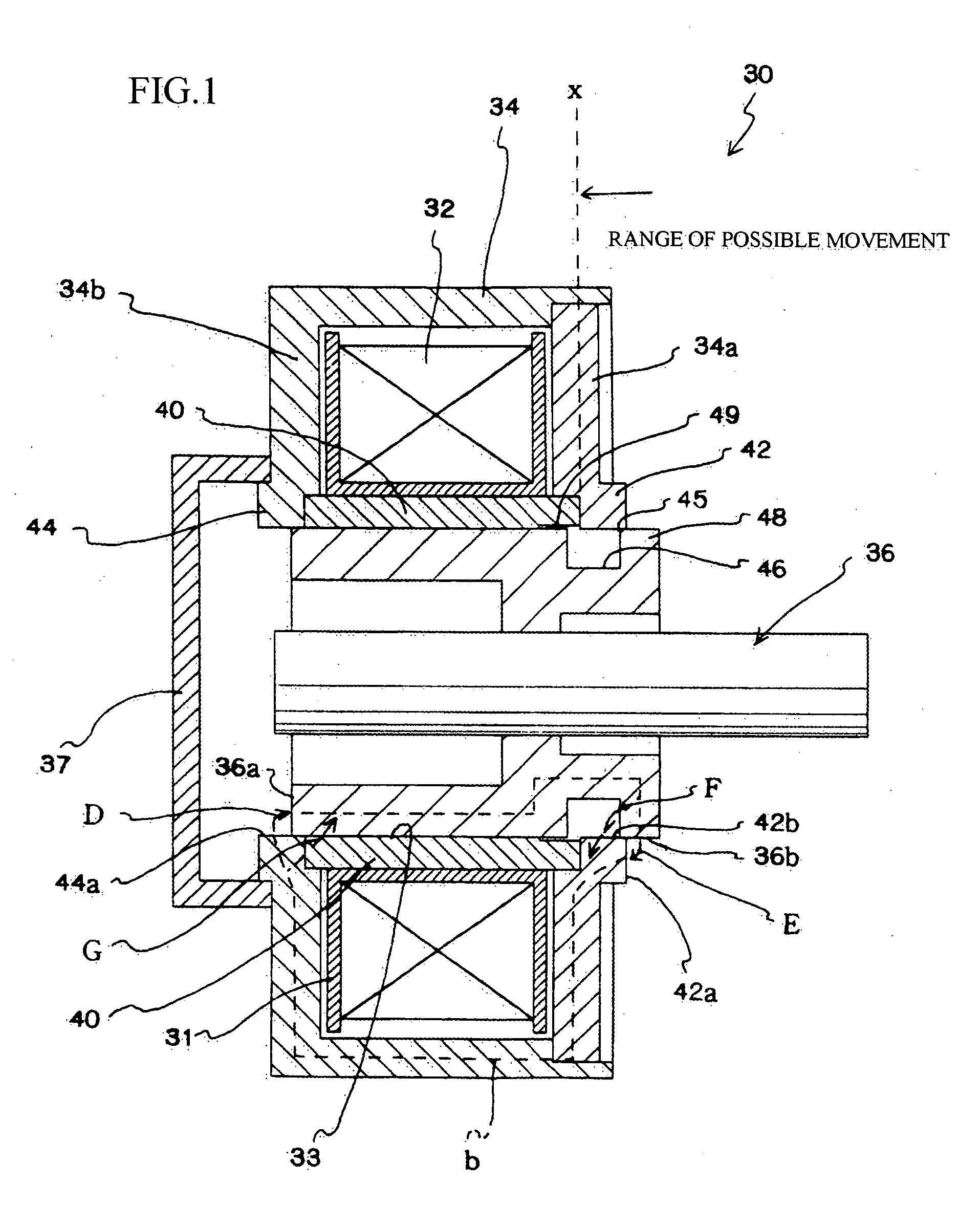
[0072] Next, a second embodiment where the formation positions of the groove and the tooth parts differ to the first embodiment described above will be described with reference to FIG. 2. It should be noted that some components that are the same as in the embodiment described above have been designated the same reference numerals and description thereof has been omitted.

[0073] In the present embodiment, the parameters n, m given in the patent claims are set so that n=1 and m=0.

[0074] The yoke 54 includes an upper yoke 54a and a lower yoke 54b.

[0075] A groove 56 is formed in a facing surface 52 on an inner wall surface of the upper yoke 54a that protrudes into the enclosure 33.

[0076] The groove 56 is formed so as to be concave in a direction away from the outer circumferential surface 36b of the slider 36 and is formed in a circle around the inner circumference of the facing surface 52.

[0077] The respective ends of the groove 56 are formed as a tooth part 58 and a tooth part 59....

third embodiment

[0087] Next, a third embodiment where the formation positions of the tooth parts differ to the first and second embodiments described above will be described with reference to FIG. 3. It should be noted that some components that are the same as in the embodiments described above have been designated the same reference numerals and description thereof has been omitted.

[0088] In the present embodiment, the parameters n, m given in the patent claims are set so that n=1 and m=1.

[0089] In the present embodiment, in addition to the construction of the second embodiment, a groove 70 is formed in the facing surface 55 of the lower yoke 54b and a tooth part 72 and a tooth part 74 that act as magnetic poles are provided at both ends of the groove 70.

[0090] A groove 76 is also formed in the outer circumferential surface 36b of the slider 36 at a position facing the facing surface 55 of the lower yoke 54b.

[0091] A tooth part 78 is provided on the other end-side of the groove. The tooth part...


PUM


Abstract

A solenoid that has a small body and increased propulsion in a controlled range is provided. The solenoid is characterized by being provided with a bearing 40 formed of a nonmagnetic body, n (where n is a positive integer of zero or above) grooves 56 and n+1 tooth parts 58 that are adjacent to the grooves 56 and function as magnetic poles being provided in a facing surface 52 of a first upper yoke 54a, m (where m is a positive integer of zero or above) grooves 70 and m+1 tooth parts 72, 74 that are adjacent to the grooves 70 and function as magnetic poles being provided in a facing surface 55 of a second upper yoke 54b, n+1 grooves 56 and n+1 tooth parts 58, 59 that are adjacent to the grooves 56 and function as magnetic poles being provided in a surface 52 of the slider 36 that faces the first upper yoke 54a, and m grooves 76 and m tooth parts 78 that are adjacent to the grooves 76 and function as magnetic poles being provided in a surface 55 of the slider 36 that faces the second upper yoke 54b.

Description

TECHNICAL FIELD [0001] The present invention relates to a solenoid used as an actuator. BACKGROUND ART [0002]FIGS. 5 and 6 show constructions of typical solenoids that are conventionally known. [0003] A solenoid 10 includes an excitation coil 12, a yoke 14 that is assembled so as to surround the excitation coil 12, a bearing 15 disposed in a central part of the excitation coil 12, and a slider 16 (a moving iron core or plunger) that is guided in a sliding state by the bearing 15 (see FIGS. 1 and 2, etc., of Japanese Laid-Open Patent Publication No. H05-211744). [0004] The yoke 14 is constructed of at least two members, an upper yoke 14a and a lower yoke 14b, with the upper yoke 14a being disposed at one end and the lower yoke 14b being provided so as to close the other end of an enclosure 19 for the slider 16 so as to limit the movement in a direction A of the slider 16. [0005] A surface 14c of the lower yoke 14b facing the other end-end surface 16a of the slider 16 functions as a f...

Claims


Application Information

Patent Timeline
IPC IPC(8): H01F7/08H01F7/13H01F7/16
CPCH01F7/081H01F7/1607H01F7/13
Inventor OKUBO, MASASHI
Owner SHINANO KENSHI
Why Eureka
Try Eureka