Interactive wireless tag location and identification system

a wireless tag and wireless technology, applied in the direction of instruments, electrical signalling details, burglar alarm mechanical actuation, etc., can solve the problems of inability to communicate the location limitations of the conventional rfid tag, etc., and achieve the effect of augmenting the environmen

Inactive Publication Date: 2006-01-05
MITSUBISHI ELECTRIC RES LAB INC
View PDF8 Cites 104 Cited by
  • Summary
  • Abstract
  • Description
  • Claims
  • Application Information

AI Technical Summary

Benefits of technology

[0025] The invention provides a versatile framework for selecting tags, identifying tags, collecting tag data, displaying information related to the tags, and interacting with the data. The invention uses projected illumination to select tags. A 3D coordinate frame is generated to locate the tags. Tag data can be projected directly onto object surfaces to augment the environment.

Problems solved by technology

Conventional RFID tags have limitations.
A conventional RFID tag cannot communicate its location.

Method used


Image

  • Interactive wireless tag location and identification system
  • Interactive wireless tag location and identification system
  • Interactive wireless tag location and identification system

Examples


Embodiment Construction

[0028] System Structure

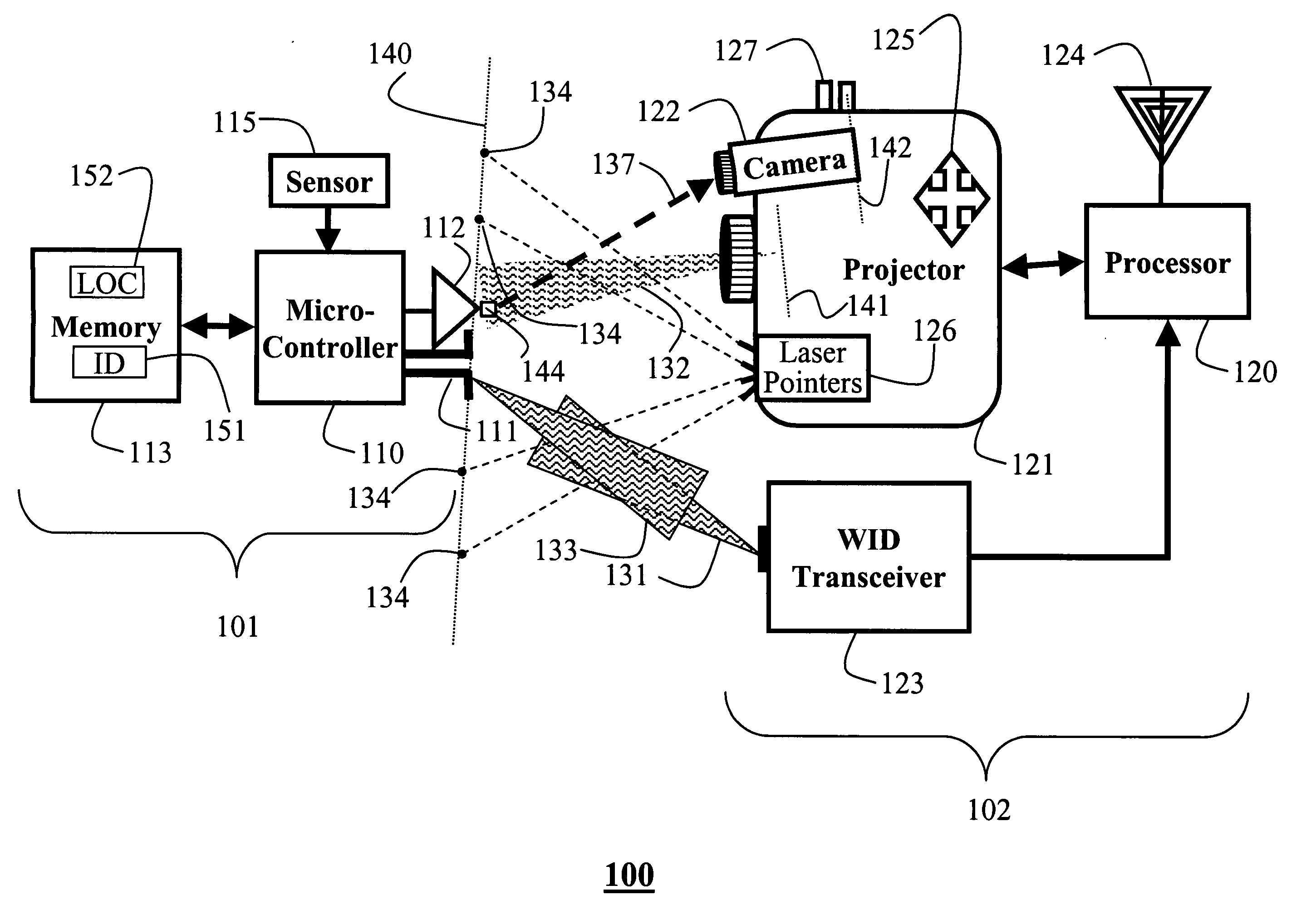
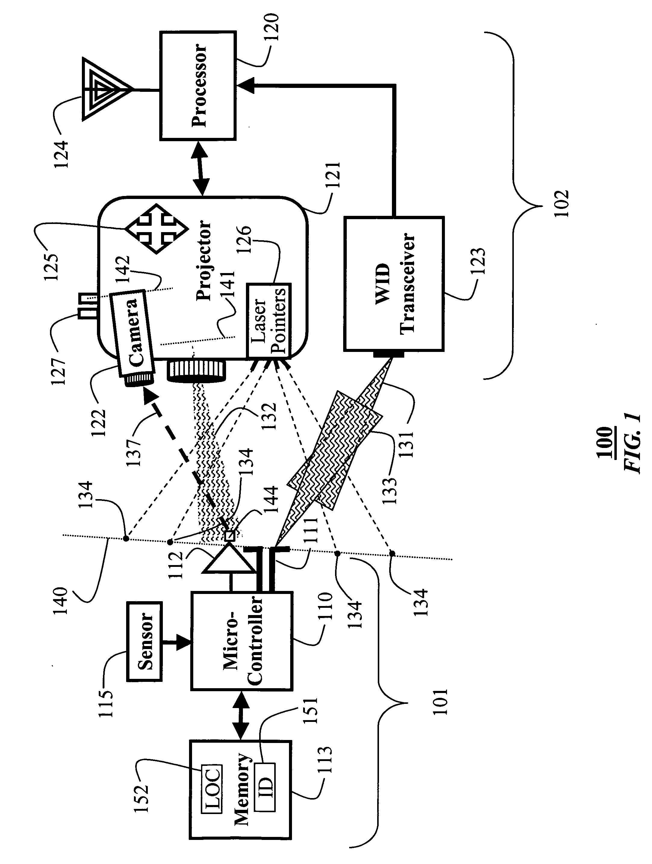
[0029] As shown in FIG. 1, an interactive tag location and identification system 100 according to our invention includes a tag 101 and a controller 102. We use the word ‘controller’ to indicate that the system 100 can perform functions other than simply reading the identification of the tag 101. The additional functionality of the interactive system according to our invention is described in detail below. As an advantage, the added functionality enables a whole new set of interactive applications.

[0030] Tag

[0031] The tag 101 includes a microcontroller 110 connected to a transducer 111, a photo-sensor 112, a memory 113, and optionally, an environment sensor 115. Typically, the tag 101 is mounted so that the sensitive components, i.e., the transducer 111 and sensors 112 and 115 are at or near an external physical surface 140, such as the surface of a box containing goods, or a wall. The memory stores data characterizing the tag and its use in a particular env...


PUM


Abstract

A wireless location and identification system includes a controller and a tag. The controller has a projector configured to generate a unique temporal sequence of light intensities for each pixel in an output image of the projector and a wireless transceiver configured to emit an output signal and receive an input signal. The tag includes a photo-sensor configured to sense the unique temporal sequence of light intensities of a particular pixel, a transducer configured to receive the output signal from the transceiver, and a means for modulating, according to the unique temporal sequence of light intensities, the input signal for the transceiver in response to receiving the output signal and sensing the unique temporal sequence of light intensities of the particular pixel to indicate a location of the tag to the controller.

Description

FIELD OF THE INVENTION [0001] The invention relates generally to identification tags and readers, and more particularly to tags that can be located and identified selectively. BACKGROUND OF THE INVENTION [0002] Over the years, computer applications have moved from highly centralized mainframes to the desktop. More recently, computing power has moved to mobile devices, such as cellular telephones, personal digital assistants, and sensors embedded unobtrusively in the environment and objects placed in the environment. [0003] One example of this application uses radio-frequency identification (RFID) tags, see Want, “RFID, A Key to Automating Everything,”Scientific American, vol. 290(1), 56-65, 2003. RFID tags can be as small as a grain of rice, are cheap, e.g., a fraction of a dollar, and can transmit a unique identity to a tag-reader over a range in meters. [0004] Conventional radio-frequency identification (RFID) tags are used to identify objects, including animals and people. RFID t...

Claims


Application Information

Patent Timeline
Patent Type & Authority Applications(United States)
IPC IPC(8): G08B13/14
CPCG01S5/16G06K19/0728G06K19/0723G06K7/10079
Inventor RASKAR, RAMESHBEARDSLEY, PAUL A.BAAR, JEROEN VANDIETZ, PAUL H.
Owner MITSUBISHI ELECTRIC RES LAB INC
Why Eureka
Try Eureka