Screen, fresnel lens sheet used therefor, and image display apparatus using the same

a technology of image display apparatus and lens sheet, which is applied in the direction of optics, projectors, instruments, etc., can solve the problems of reducing efficiency, increasing loss, and reducing the brightness of the upper left and right edges of the screen, and achieves the effect of reducing the size of the image display apparatus and high image quality

Active Publication Date: 2006-01-05
MAXELL HLDG LTD
View PDF5 Cites 9 Cited by
  • Summary
  • Abstract
  • Description
  • Claims
  • Application Information

AI Technical Summary

Benefits of technology

[0017] According to the present invention, it is possible to thin down a

Problems solved by technology

Further thinning-down of the set abruptly increases the loss and poses the problem that the upper left and right ends of the screen decrease in brightness.
The configuration described in the above Patent Document, however, poses the problem that since refractive prisms are provided on the light entrance surface of the Fresnel lens sheet, efficiency decreases and, in

Method used


Image

  • Screen, fresnel lens sheet used therefor, and image display apparatus using the same
  • Screen, fresnel lens sheet used therefor, and image display apparatus using the same
  • Screen, fresnel lens sheet used therefor, and image display apparatus using the same

Examples


Embodiment Construction

[0028] Embodiments of the present invention are described below referring to the accompanying drawings.

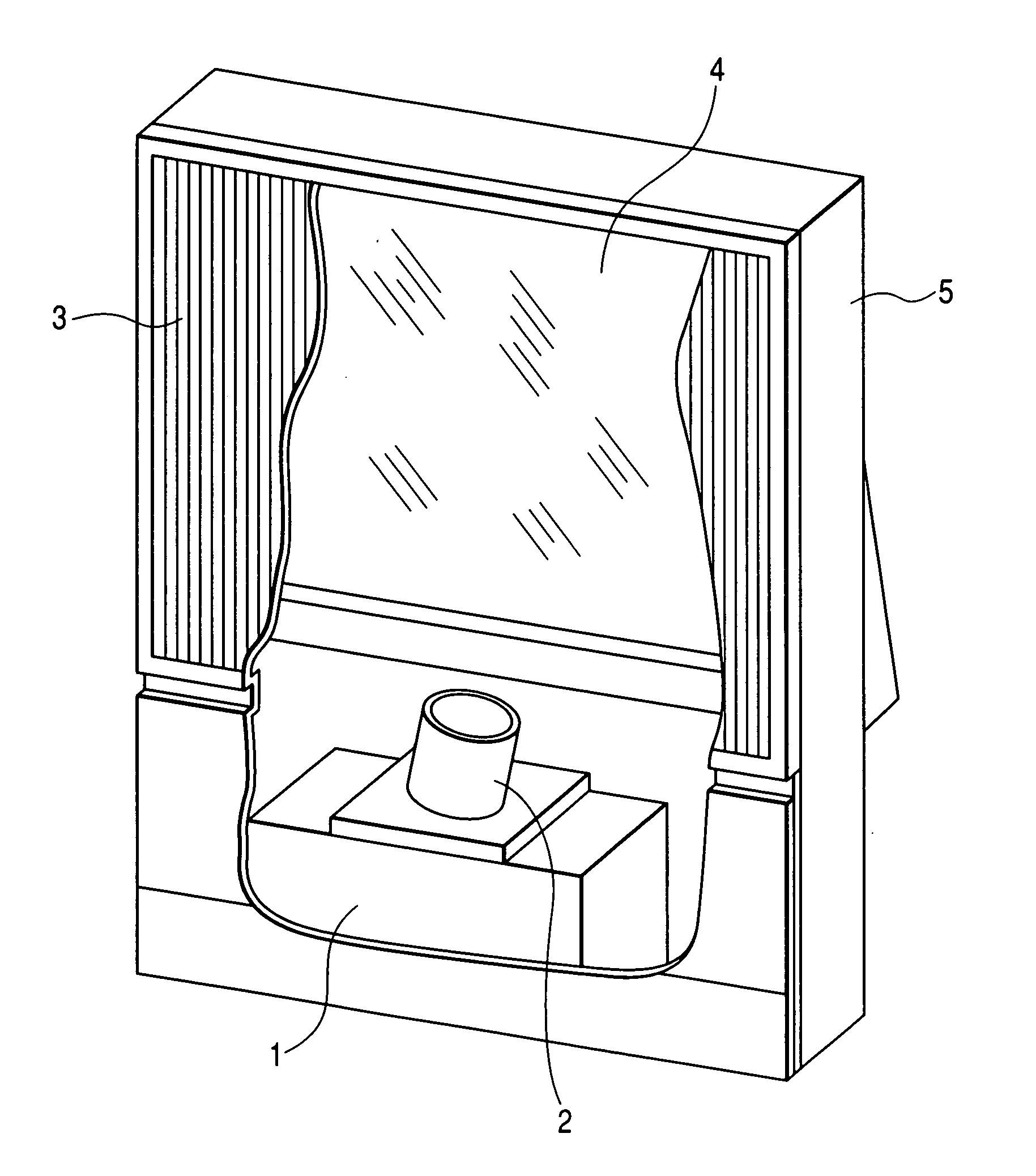
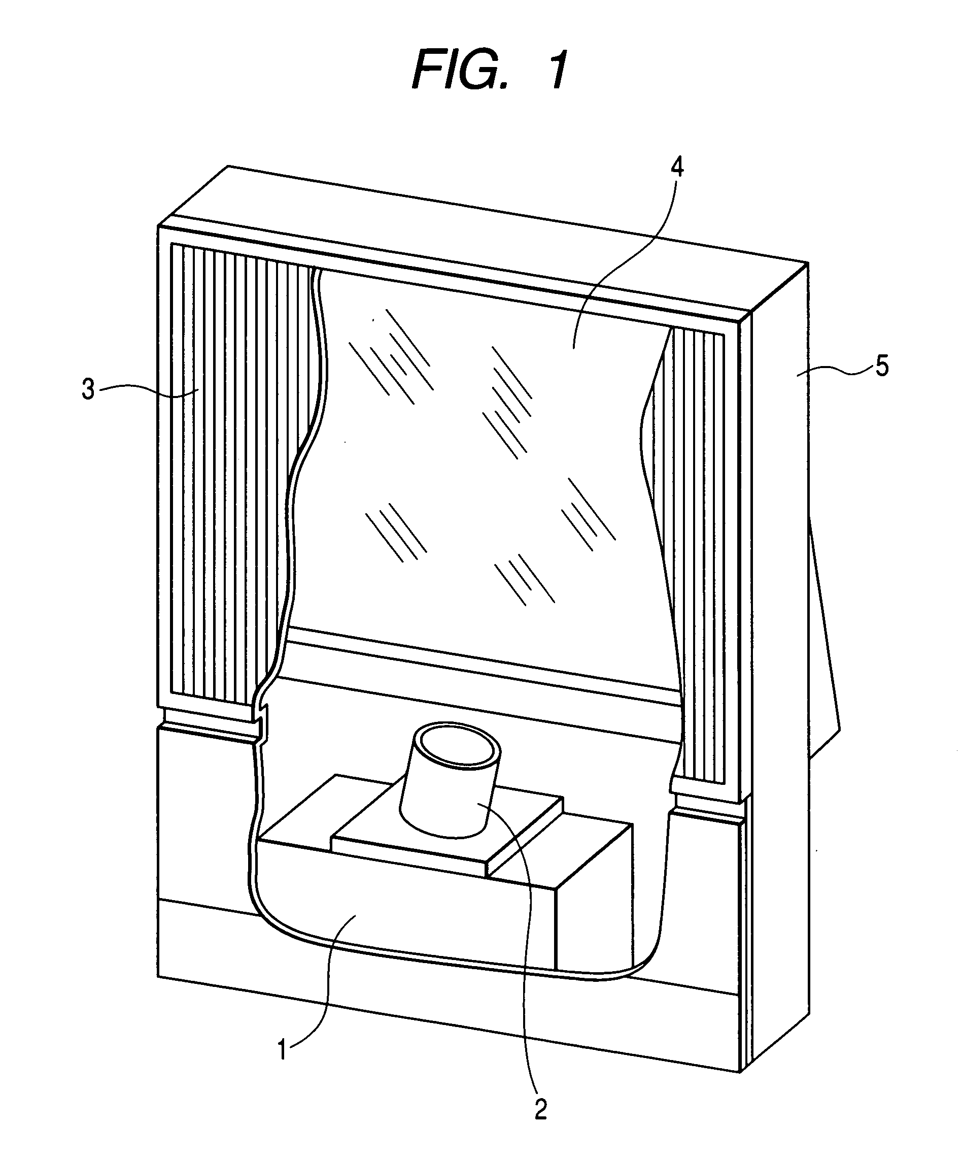
[0029]FIG. 1 is a perspective view showing partly in section an example of an image display apparatus according to the present invention. An image generation source 1 is constituted by a projection cathode-ray tube or a reflective or transmissive liquid-crystal panel, an image modulation element with a plurality of very small mirrors, such as a display element, and other elements. The image generation source 1 displays a compact image. A projection lens 2 that is an optical component projects the image onto a back-projection screen 3. Since the projection lens is generally long in projection distance, a reflecting mirror 4 is provided halfway on an optical path of the projection lens in order to reduce a depth of the image display apparatus. These elements are fixed to required positions inside an enclosure 5.

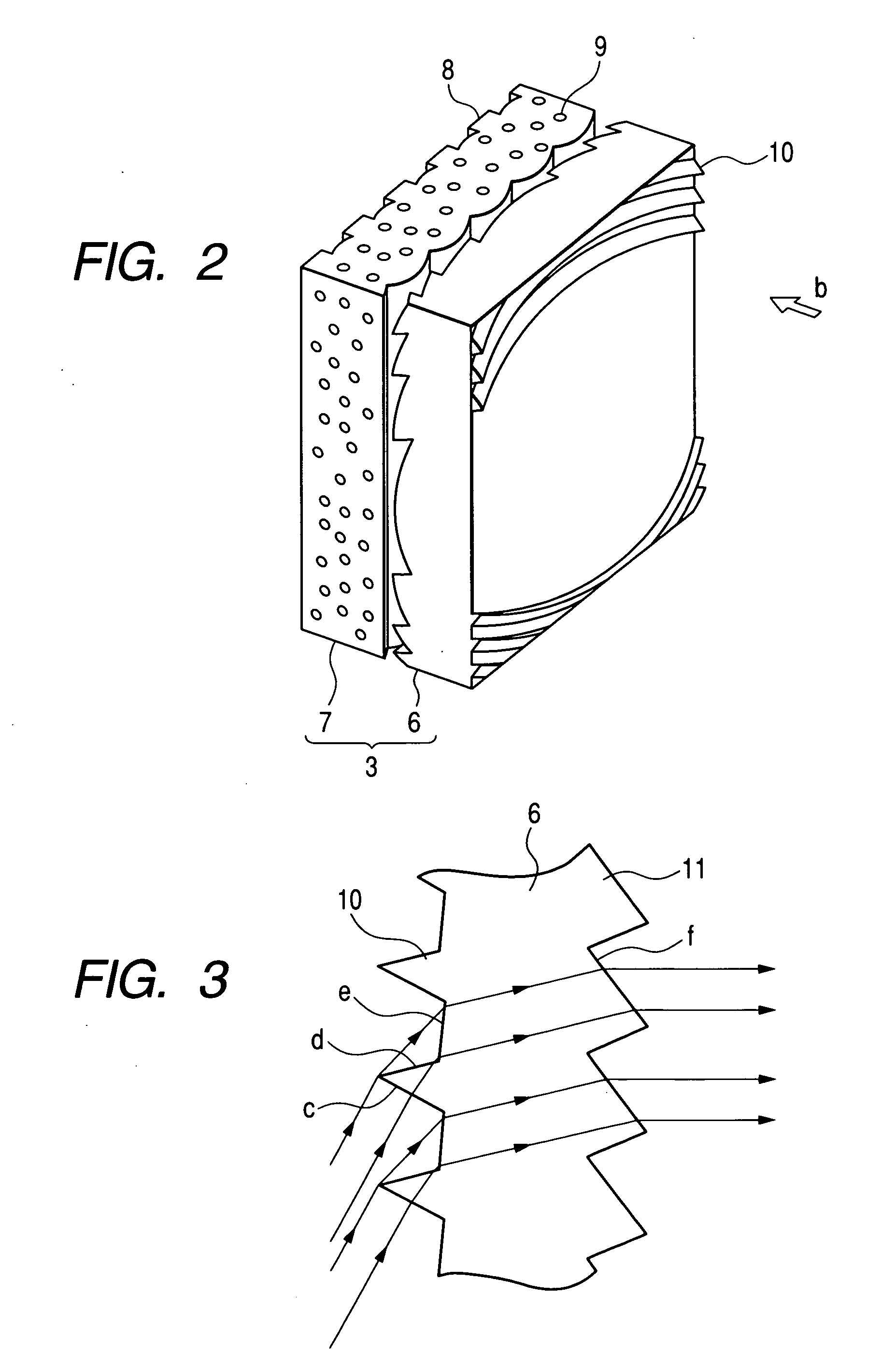
[0030]FIG. 2 is a schematic view showing a structure of the back-projec...


PUM


Abstract

Images that are bright even on the periphery of a transmissive screen are obtained by reducing reflection loss of the screen when the screen incident angle of the image light entering the upper left and right ends of the screen increases. Incident-side prisms (10), each having at least a plane-of-incidence (c) onto which light comes in, an exit face (d) from which the light that has come in from the plane-of-incidence exits after being refracted, and a refractive face (e) on which the light that has exited from the exit face is refracted and then guided to the image-viewing side of the Fresnel lens sheet (6), are provided in the range where the incident angle of the incoming light becomes equal to or greater than approximately 40 degrees.

Description

CLAIM OF PRIORITY [0001] The present application claims priority from Japanese Application serial no. JP 2004-195130 field on Jul. 1, 2004, the content of which is hereby incorporated by reference into this application. BACKGROUND OF THE INVENTION [0002] (1) Field of the Invention [0003] The present invention relates to an image display apparatus for enlarging and projecting the image generated by an image generation source, and displaying this image in an enlarged and projected form on a transmissive screen. The invention also relates to the screen and Fresnel lens sheet used for the image display apparatus. [0004] (2) Description of the Related Art [0005] A projection-type image display apparatus (hereinafter, may be called the set) enlarges and projects, via a projection lens and / or the like, the image displayed by a compact image generation source such as a projection-type cathode-ray tube, liquid-crystal display apparatus, or the like, sends the enlarged and projected image to ...

Claims


Application Information

Patent Timeline
IPC IPC(8): G02F1/1335G02B3/00G02B3/08G02B5/02G03B21/62G03B21/625
CPCG02B3/005G02B3/08G02B5/0231G03B21/625G02B5/0278G02B5/045G03B21/10G02B5/0242
Inventor OHISHI, TETSUYOSHIKAWA, HIROKIHIRATA, KOJIIMAFUKU, DAISUKE
Owner MAXELL HLDG LTD
Why Eureka
Try Eureka