Measurement of slider clearance by inducing collision of the slider with disk surface

a slider and disk surface technology, applied in the field of measuring the clearance of sliders flying over the disk surface, can solve the problems of loose accuracy below 10 nm, inability to make bumps, and becoming increasingly difficult to measure the actual fly height of sliders, etc., and achieve the effect of stable fly heigh

Active Publication Date: 2006-01-05
WESTERN DIGITAL TECH INC
View PDF13 Cites 19 Cited by
  • Summary
  • Abstract
  • Description
  • Claims
  • Application Information

AI Technical Summary

Benefits of technology

[0013] A method is presented for measuring the clearance of a slider over a rotating disk by inducing a collision between the slider and the disk. The normal flying height of the slider is established by operating the disk drive or test stand to achieve a stable fly height. The slider is then driven into a collision with the rotating disk surface by applying a DC or AC voltage between the slider and the disk. The collision is typically nondestructive since the duration is very short. The clearance data can be extracted from the induced collision by measuring a parameter, such as the change in the amplitude of the readback signal from the magnetic sensor, which is related to fly-height at the normal fly-height and at the disk surface. The two data points can then be used to derive the clearance. One embodiment uses a single beam interferometer to derive the vibrational displacement of the collision event. By forcing a transition of the slider from a normal flying height to a collision with the disk the method creates a vibrational event that can be measured by the interferometer and from which the displacement can be derived. The displacement during the transition event is the clearance of the slider. The technique is extremely sensitivity at very low fly-heights (less than 7 nm) and can achieve accuracy which is significantly better than the accuracy of prior art white light interferometry. In a second embodiment the change in the amplitude of the readback signal from the magnetic sensor is used with the Wallace Spacing Loss Equation to convert the change in amplitude into a distance which is the clearance. A disk drive is described which uses the readback signal to make a self-measurement of the clearance of its sliders by including means to apply the voltage to the suspension and to detect the collision point in the signal from the magnetic sensor.

Problems solved by technology

Accordingly, it is becoming increasingly difficult to measure the actual fly-height of sliders.
The most common technique using white light interferometry works adequately for a fly-height above 10 nm, but it looses accuracy below 10 nm.
Since it has proved impractical to make bumps below 5 nm in height, this particular technique looses accuracy for very small fly-heights.

Method used


Image

  • Measurement of slider clearance by inducing collision of the slider with disk surface
  • Measurement of slider clearance by inducing collision of the slider with disk surface
  • Measurement of slider clearance by inducing collision of the slider with disk surface

Examples


Embodiment Construction

[0021] The method of the invention is useful for testing sliders during design or manufacturing. Testing of the flying characteristics of sliders during a design phase or during manufacturing is typically done after the slider has been integrated into a suspension.

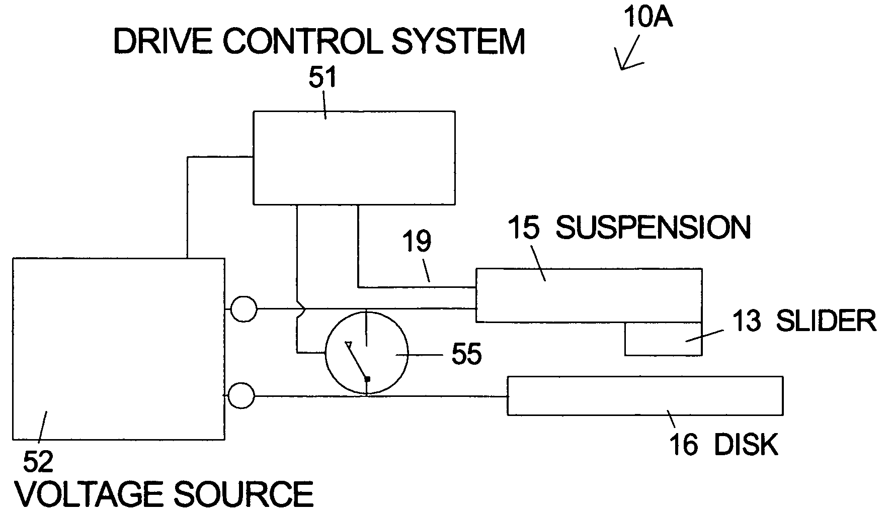
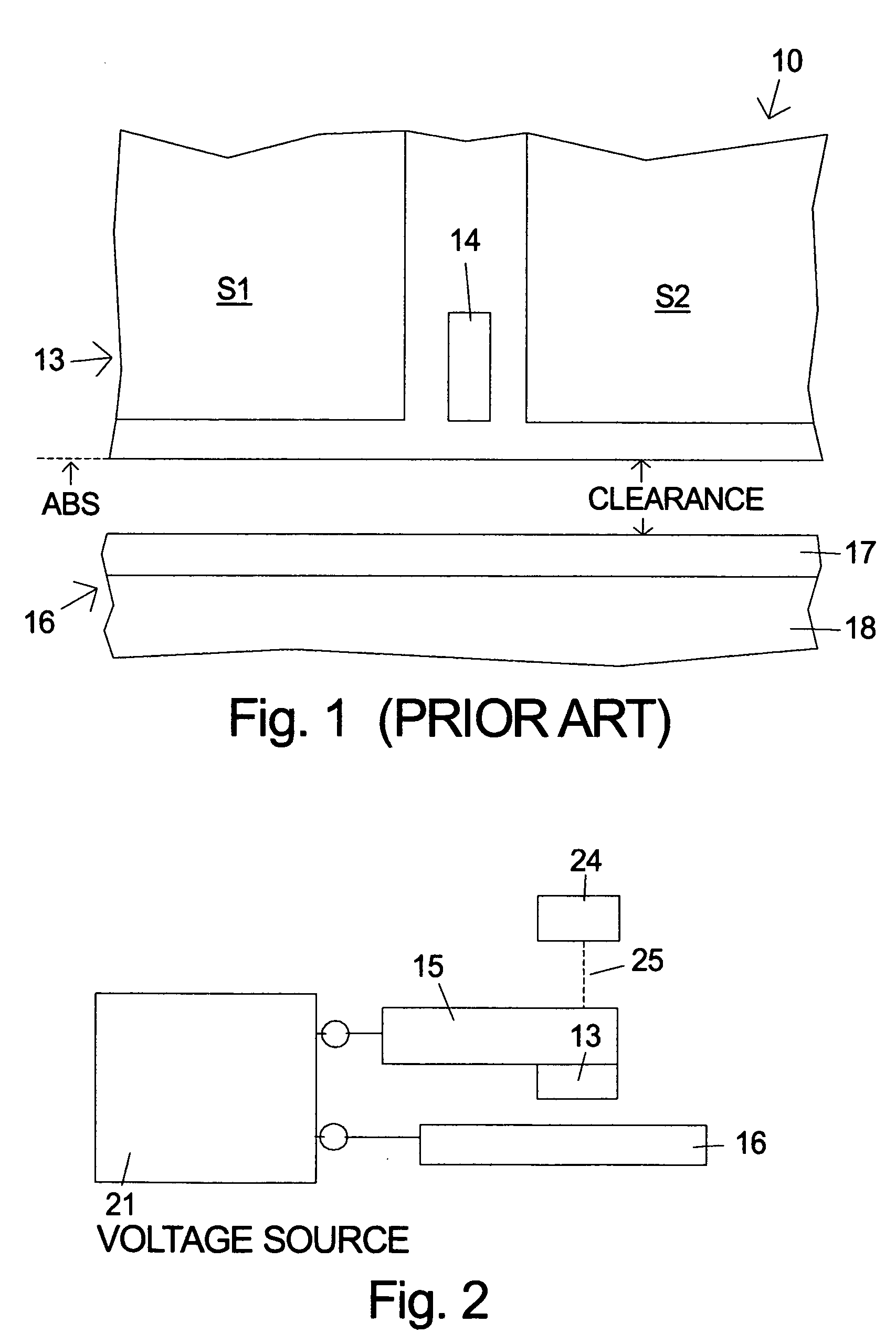
[0022]FIG. 2 illustrates a setup for the clearance measurement using an interferometer 24 according to the invention. A voltage source 21 is connected between the suspension 15 on which slider 13 is mounted and disk 16. The testing can be performed on slider and disk in a standard disk drive with some alterations. In a completed disk drive the suspension 15 and the disk 16 are typically connected to a common ground. This ground connection for the slider must be broken to allow a voltage to develop across the air-bearing between the slider and the disk. The electrical connections to the slider 13 are made through the suspension 15 which supports the slider. The measurement can also be made in test fixture where the suspens...


PUM

PropertyMeasurementUnit
fly-heightaaaaaaaaaa
heightaaaaaaaaaa
voltageaaaaaaaaaa

Abstract

A method for measuring the clearance of a slider over a rotating disk by inducing a collision between the slider and the disk is described. After the normal flying height of the slider is established, the slider is driven into a collision with the rotating disk surface by applying a DC or AC voltage between the slider and the disk. The clearance data can be extracted from the induced collision by measuring a parameter, such as the change in the amplitude of the readback signal from the magnetic sensor, which is related to fly-height at the normal fly-height and at the disk surface. The two data points can then be used to derive the clearance. One embodiment uses a single beam interferometer to derive the vibrational displacement of the collision event.

Description

FIELD OF THE INVENTION [0001] The invention relates to methods for measuring parameters of sliders and disks used in magnetic storage devices, and more particularly to measuring the clearance of sliders flying over a disk. BACKGROUND OF THE INVENTION [0002] In a typical prior art magnetic disk recording system 10 as illustrated in FIG. 1 a slider 13 containing magnetic transducers for reading 14 and writing (not shown) magnetic transitions is urged toward the rotating disk 16 by a suspension (not shown). The magnetic sensor 14 is flanked by shields S1 and S2. As the disk rotates an air-bearing develops under the slider and causes it to fly. The distance between the slider and the disk surface is the clearance. The disk 16 typically includes a thin film overcoat 17 and a set of thin films 18 which include one or more ferromagnetic layers in which information is recorded. A disk drive can contain multiple disks and multiple sliders. [0003] A lower slider fly-height is required for hig...

Claims


Application Information

Patent Timeline
Patent Type & Authority Applications(United States)
IPC IPC(8): G11B21/02G11B27/36
CPCG11B5/455G11B2220/20G11B27/36
Inventor FONG, WALTONGILLIS, DONALD RAYKNIGGE, BERNHARD E.PIT, REMMELTSUK, MIKE
Owner WESTERN DIGITAL TECH INC
Why Eureka
Try Eureka