Method of manufacturing a magnetic slider head

a slider head and magnetic head technology, applied in the direction of maintaining head carrier alignment, insulation conductor/cable, instruments, etc., can solve the problem of reducing the generated lifting force, and the prior art magnetic head sliders do not solve this problem. , to achieve the effect of reducing peripheral speed, reducing lifting force, and stable fly height of the magnetic head slider

Inactive Publication Date: 2009-11-10
WESTERN DIGITAL TECH INC
View PDF7 Cites 2 Cited by
  • Summary
  • Abstract
  • Description
  • Claims
  • Application Information

AI Technical Summary

Benefits of technology

[0011]According to the present invention, it is possible to generate a large lifting force for the magnetic head slider and thereby achieve a stable fly height of the magnetic head slider even with a reduced peripheral speed resulting from the trend toward magnetic disks having smaller diameters. Furthermore, it is possible to provide a manufacturing method for the magnetic head slider.

Problems solved by technology

The techniques, however, do not address whatsoever the problem of the reduced lifting force generated by the magnetic head slider due to the slower peripheral speed which results from the trend toward smaller diameters of the magnetic disks.
The magnetic head sliders of the prior art do not solve this problem.

Method used


Image

  • Method of manufacturing a magnetic slider head
  • Method of manufacturing a magnetic slider head
  • Method of manufacturing a magnetic slider head

Examples


Embodiment Construction

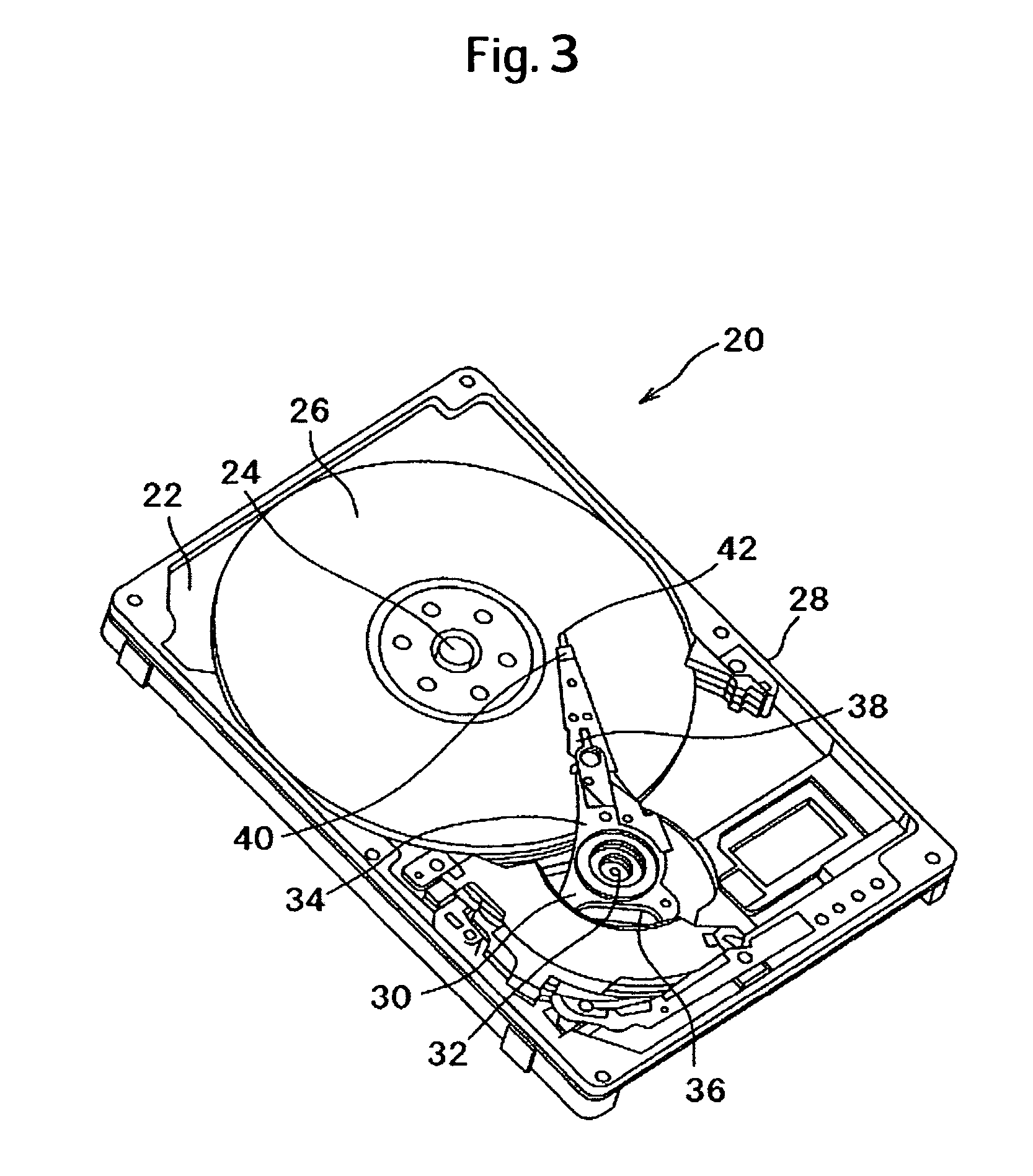
[0022]Specific embodiments to which the present invention is applied will be described below with reference to the accompanying drawings. A general construction of a magnetic disk drive, in which a magnetic head slider is mounted, will be first described with reference to FIG. 3. A magnetic disk drive 20 includes a base 22, a spindle motor 24 fixed to the base 22, and an actuator 30. The spindle motor 24 is mounted with at least one magnetic disk 26. The actuator 30 includes a head arm 34 that swings about a pivot 32 and a voice coil motor (VCM) 36. One end of a suspension 38 is mounted on the head arm 34, while a magnetic head slider 40 is mounted on the other end of the suspension 38. A lift tab 42 is formed at a leading end of the other end of the suspension 38. In addition, a load / unload mechanism 28 is secured to the base 22. When current is passed through the VCM 36, the head arm 34 swings about the pivot 32. This correctly locates the magnetic head slider 40 mounted on the su...


PUM

PropertyMeasurementUnit
diameteraaaaaaaaaa
total areaaaaaaaaaaa
thickaaaaaaaaaa

Abstract

Embodiments of the invention relate to manufacturing method of a magnetic head slider which flies stably even with a reduced peripheral speed resulting from a trend toward a magnetic disk having a smaller diameter. According to one embodiment, a method of manufacturing a magnetic head slider comprises forming a leading side rail surface and a trailing side rail surface, a leading stepped bearing surface and a trailing stepped bearing surface, and a negative-pressure groove surface on an air bearing surface through etching, forming a first stepped surface on the leading side rail surface through sputtering, and forming a second stepped surface by forming a carbon layer on the first stepped surface through sputtering. The first stepped surface has a first height with respect to the leading side rail surface and the second stepped surface has a second height with respect to the first stepped surface.

Description

CROSS-REFERENCES TO RELATED APPLICATIONS[0001]This application claims priority from Japanese Patent Application No. JP2005-201215, filed Jul. 11, 2005, the entire disclosure of which is incorporated herein by reference.BACKGROUND OF THE INVENTION[0002]The present invention relates to a magnetic head slider capable of maintaining a stable fly height even with a peripheral speed reduced due to the reduction in diameter of a magnetic disk, and a manufacturing method therefor.[0003]A magnetic disk drive uses a magnetic head slider that flies above a spinning magnetic disk recording medium (magnetic disk), while maintaining a microscopic distance (a flying height) therefrom. The magnetic disk drive is required to make the magnetic head slider fly in a low flying state, in which the magnetic head slider is as close as possible to the magnetic disk, in order to increase storage capacity. To achieve such a stringent requirement for the low flying height, a negative pressure type magnetic he...

Claims


Application Information

Patent Timeline
Patent Type & Authority Patents(United States)
IPC IPC(8): G11B5/127H04R31/00
CPCG11B5/6005Y10T156/11Y10T29/49025Y10T156/1082Y10S438/976Y10T29/49048Y10T29/49052Y10T29/49037Y10T29/49041
Inventor TANIGUCHI, YOSHIHIROTAKEUCHI, YOSHINORI
Owner WESTERN DIGITAL TECH INC
Why Eureka
Try Eureka