Method and system for illuminating an interior space with mostly indirect lighting

a technology for interior spaces and indirect lighting, applied in the field of indirect lighting systems and methods, can solve the problems of difficult reconfiguration of space use, configuration and installation, etc., and achieve the effect of uniform illumination, convenient retrofitting, and pleasing aesthetic appearan

Inactive Publication Date: 2006-01-05
ABL IP HLDG
View PDF16 Cites 5 Cited by
  • Summary
  • Abstract
  • Description
  • Claims
  • Application Information

AI Technical Summary

Benefits of technology

[0007] In a further aspect of the invention, the housing for each of the indirect fluorescent fixture elements of each lighting fixture module is made of a diffuser material—suitably opal acrylic—that receives some light from the fluorescent lamps. The result is that the fixture housings appear at least partially luminous, thereby introducing a pleasing aesthetic appearance into the visual environment. Preferably the ends of the fixture elements that extend beyond the lamp ends are painted or otherwise treated to render them opaque and therefore non-luminous. The luminous housings introduce a small percentage of direct lighting into the space, and, in combination with the geometry, spacing and size of the lighting fixture modules of the system, create a visually pleasing lighting environment that is substantially uniformly illuminated.
[0008] By providing the lighting fixture modules in an eight foot by ten foot on-center grid array, the fixture modules can be installed on the T-bars of a conventional overhead grid ceiling system having a 2′×2′ or 2′×4′ grid pattern. Also, the eight foot by ten foot on center array corresponds to the conventional center-to-center spacings of recessed down lights in a typical down lit office space using two by four foot recessed troffers. Thus, an interior space having a down light system comprised of a standard array of recessed down lights can be easily retrofitted with indirect lighting fixture modules of the invention by first hanging the modules from the grid ceiling beneath the space where the recessed down lights have been removed, and then replacing the ceiling tile or tiles above the suspended fixtures. As compared to conventional indirect lighting systems consisting of continuous rows of similar linear fixture elements (same lamps and same number of lamps), the discreet side-by-side pair of indirect lighting fixture elements of each of the lighting fixture modules of the invention will produce a better ceiling brightness distribution. The eight foot by ten foot centers of the array of fixtures have the additional advantage, as compared to continuous rows of fixtures, that the interior space can more easily be divided up by partition walls without significantly affecting the quality of the lighting environment in the divided up space.
[0012] It is a further object of the invention to provide an indirect lighting system having ceiling suspended indirect lighting modules that are aesthetically pleasing when viewed in an interior space.

Problems solved by technology

Current approaches to designing linear indirect fluorescent lighting systems suffer from the need to configure and install systems that are relatively complex to put together and install, or are visually bulky, or light up the interior space in ways that make it difficult to reconfigure the use of the space, such as by inserting or moving partition walls.

Method used


Image

  • Method and system for illuminating an interior space with mostly indirect lighting
  • Method and system for illuminating an interior space with mostly indirect lighting
  • Method and system for illuminating an interior space with mostly indirect lighting

Examples


Embodiment Construction

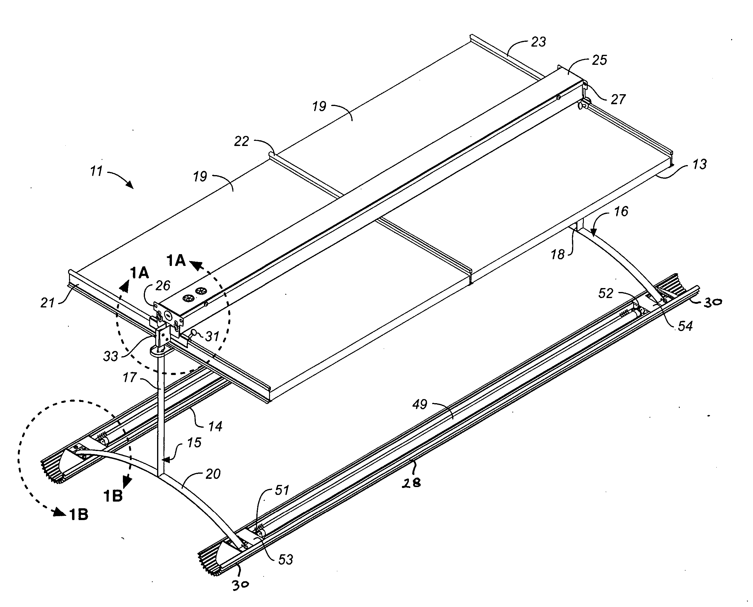
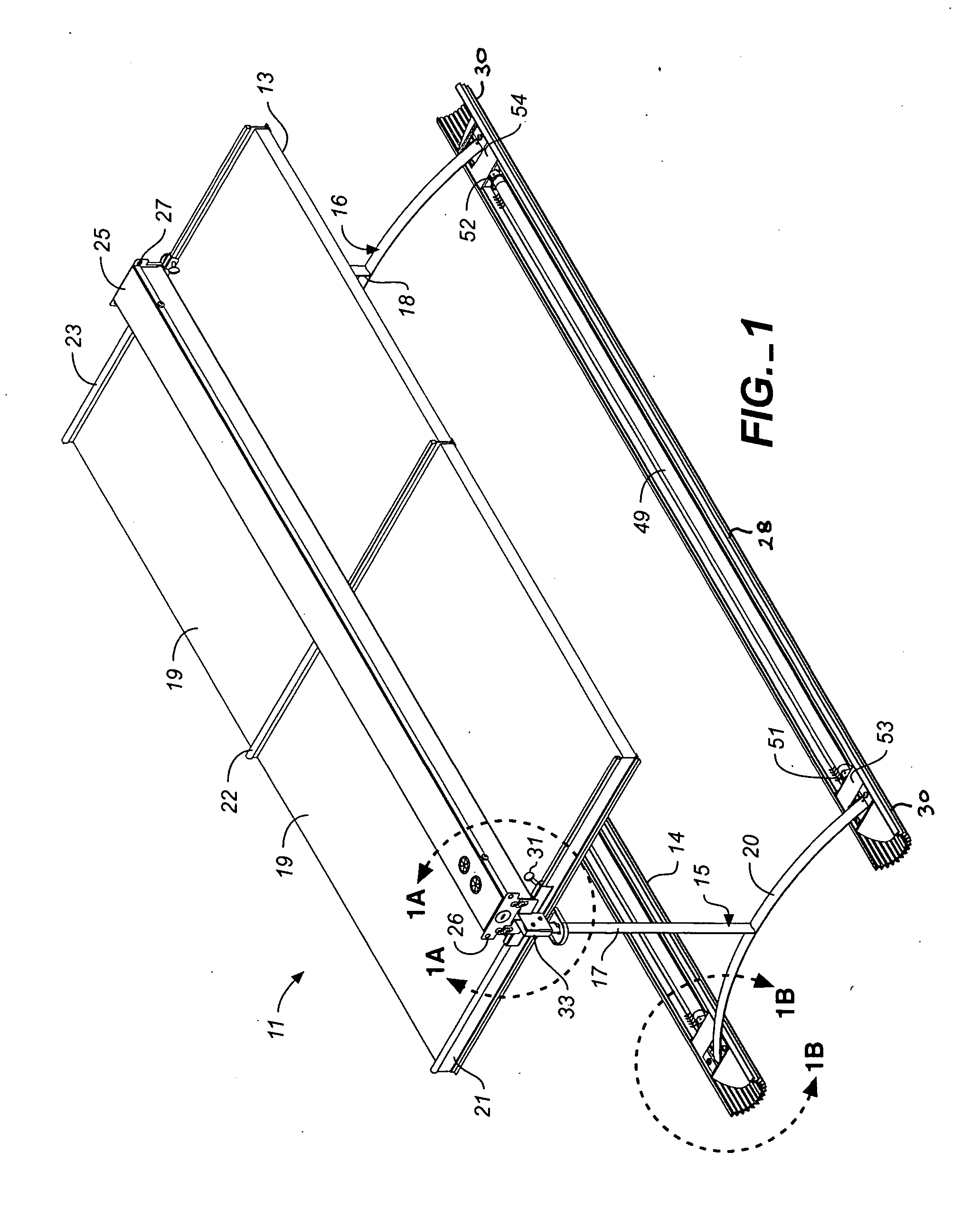
[0023] As used herein, reference to an “indirect” lighting fixture, module or element is not limited to totally indirect lighting, and shall be understood to include lighting fixtures, modules, or elements that provide up light as well as a component of down light.

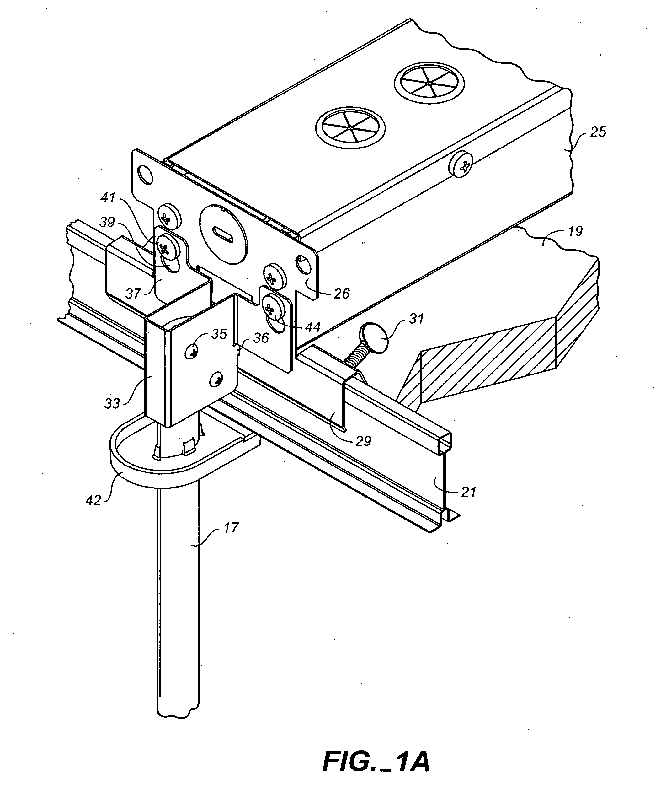
[0024] Referring to FIGS. 1, 1A, 2 and 4, an indirect lighting fixture module 11 having parallel side-by-side linear indirect fluorescent lighting fixture elements 12, 14 is shown suspended below a grid ceiling system 13 by means of two hangers 15, 16 nominally spaced apart by about four feet to correspond with the spacing T-bars of a grid ceiling, but which could have other separations for particular applications. For illustrative purposes, only a small portion of the grid ceiling system is shown in FIG. 1, namely, two tiles 19 of the grid ceiling and three parallel sections of T-bar 21, 22 and23. With two foot by two foot tiles, this section of the ceiling provides an approximately two foot by four foot profile, under w...


PUM


Abstract

A method and system for indirectly illuminating an open interior space, such as an open office, includes using individual lighting fixture modules, each comprised of at least one, and preferably a pair of side-by-side parallel linear indirect fluorescent lighting fixture elements suspended at fixed grid pattern locations beneath the ceiling of the open interior space. Each of the linear indirect lighting fixture elements of the fixture module is preferably no greater than approximately six feet in length with a suitable length being somewhat greater than four feet where a four foot lamp is used. Where the fixture elements are provided in pairs, each is suspended below the ceiling at its fixed grid location by a suitable hanger structure that maintains a spacing between the fixture elements that establishes a preferred overall fixture module with of approximately four feet. The indirect fixture modules are especially well adapted to be suspended below a grid ceiling having square or rectangular ceiling grids for supporting square or rectangular ceiling tiles, however, they can be suspended below other ceiling structures as well.

Description

CROSS-REFERENCE TO RELATED APPLICATIONS [0001] Applicants claim the benefit of U.S. provisional application No. 60 / 579,040 filed Jun. 10, 2004.BACKGROUND OF THE INVENTION [0002] The present invention generally relates to the lighting of interior spaces and, more particularly, to systems and methods for achieving indirect lighting in an interior space from ceiling suspended lighting fixtures. [0003] Illuminating interior spaces, such as open offices, using indirect lighting systems is well known. One commonly used approach to indirect lighting in open office environments is to use linear indirect fluorescent lighting wherein elongated indirect fixture elements are suspended below the ceiling and arranged in rows or grid patterns to achieve a desired lighting environment. Normally, individual fixture elements are connected together to form continuous runs of fixtures including runs that have bends or intersect one another. In a typical installation, parallel runs of fixtures are provi...

Claims


Application Information

Patent Timeline
Patent Type & Authority Applications(United States)
IPC IPC(8): G01D11/28F21S8/06F21V7/00F21V23/02
CPCF21S2/00F21S8/06F21V7/0008F21Y2103/00F21V21/112F21V23/026F21V21/02
Inventor HERST, DOUGLAS J.NGAI, PETER Y.Y.TRAN, MICHAEL TRUNGSALMAN, UTKAN
Owner ABL IP HLDG
Why Eureka
Try Eureka