
Method and apparatus for ejecting a medium

a technology of electronic equipment and ejecting medium, which is applied in the direction of digital recording, recording signal processing, instruments, etc., can solve the problems of difficult identification of parts (circular parts), poor visibility of liquid crystal display (lcd) portion due to outside light, and inability to operate smoothly. , to achieve the effect of smooth ejecting operation of the medium

Inactive Publication Date: 2006-01-05
ALPINE ELECTRONICS INC
View PDF30 Cites 21 Cited by
  • Summary
  • Abstract
  • Description
  • Claims
  • Application Information

AI Technical Summary

Benefits of technology

[0010] Accordingly, it is an object of the invention to provide an electronic apparatus that enables smooth ejection of a medium even on a crystal liquid display (LCD) with bad visibility.
[0011] Another object of the invention is to provide an electronic apparatus that can ensure identification of all eject keys for media even when the display on a touch panel surface is difficult to view.
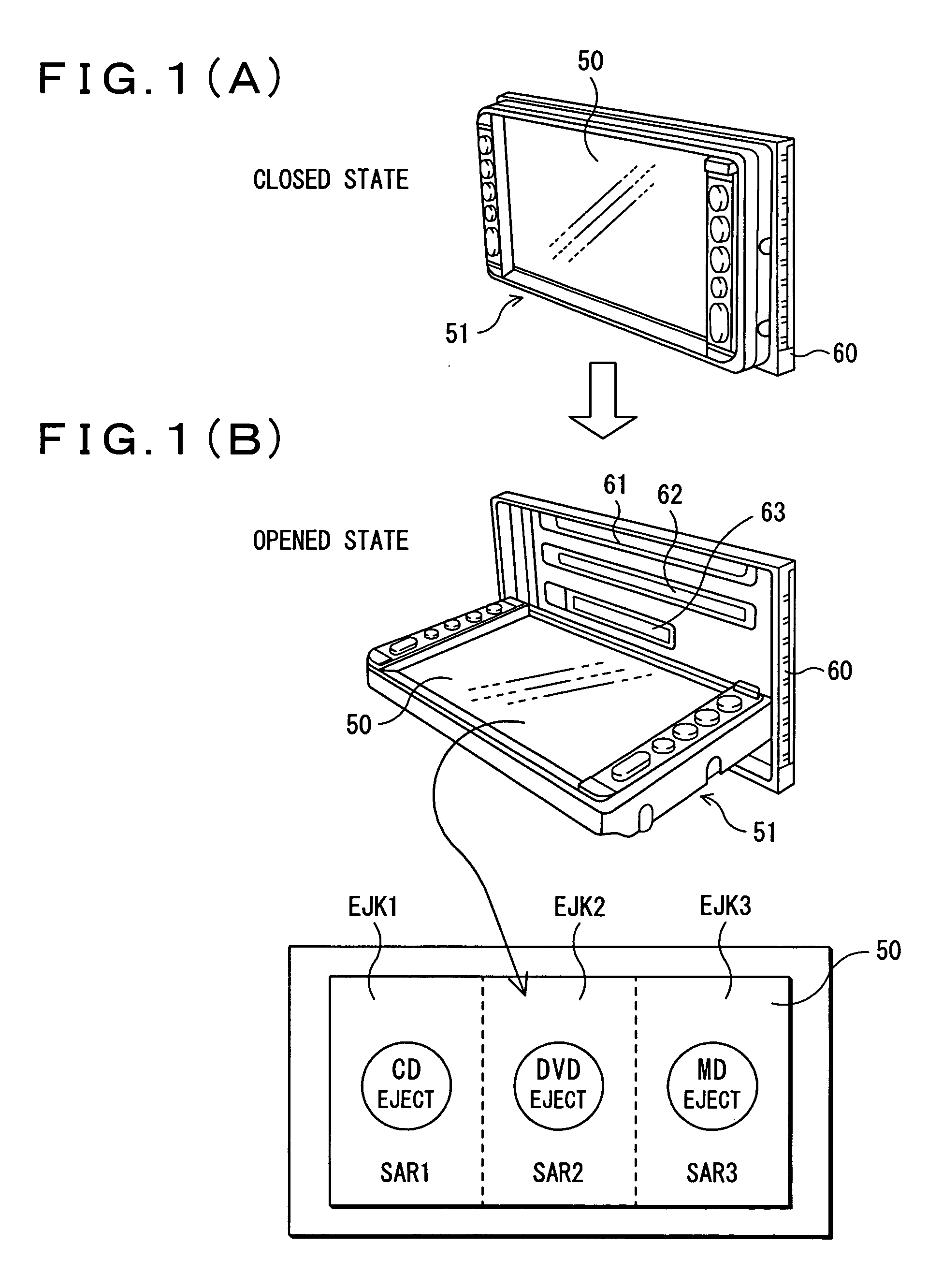
[0016] According to the embodiments described above, the entire surface of the touch panel may be used as an eject key(s), thereby surely identifying which type of medium corresponds to the eject key, even on a crystal liquid display (LCD) with bad visibility, thus resulting in a smooth eject operation of the medium.

Problems solved by technology

This structure shown in FIG. 20, however, needs a great number of keys on the body, leading to disadvantages in its operability and cost.
However, in this method, the touch panel 2 is faced upward in use as shown in FIG. 22, resulting in bad visibility of a liquid crystal display (LCD) portion due to outside light.
This makes it difficult to identify areas (circular parts) which serve as the touch switches 11 to 14, especially during a clear day, disadvantageously failing to smoothly perform an eject operation.

Method used


Image

  • Method and apparatus for ejecting a medium
  • Method and apparatus for ejecting a medium
  • Method and apparatus for ejecting a medium

Examples


first preferred embodiment

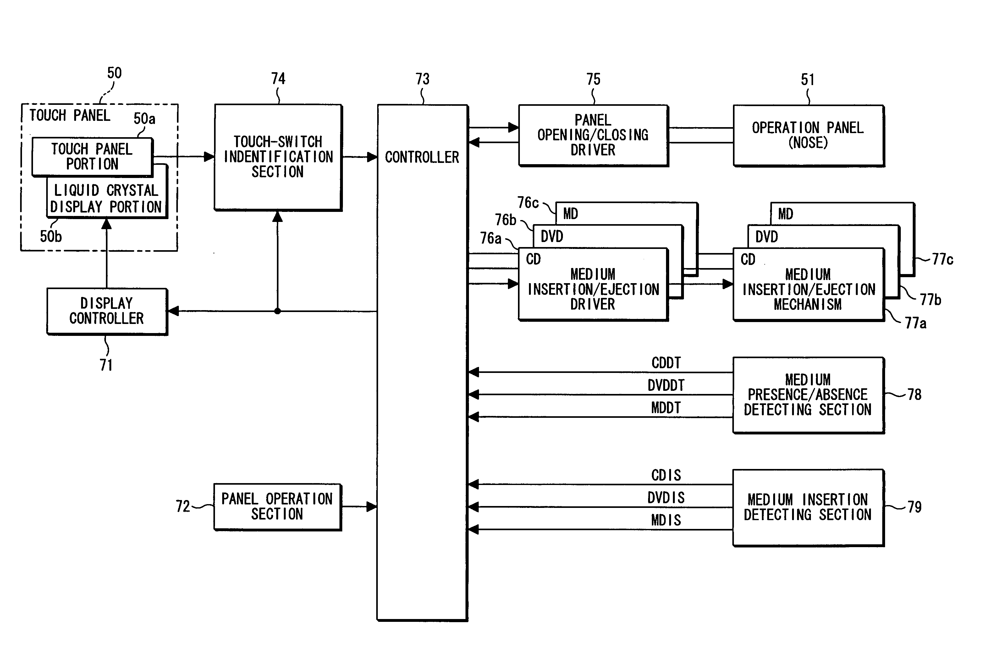
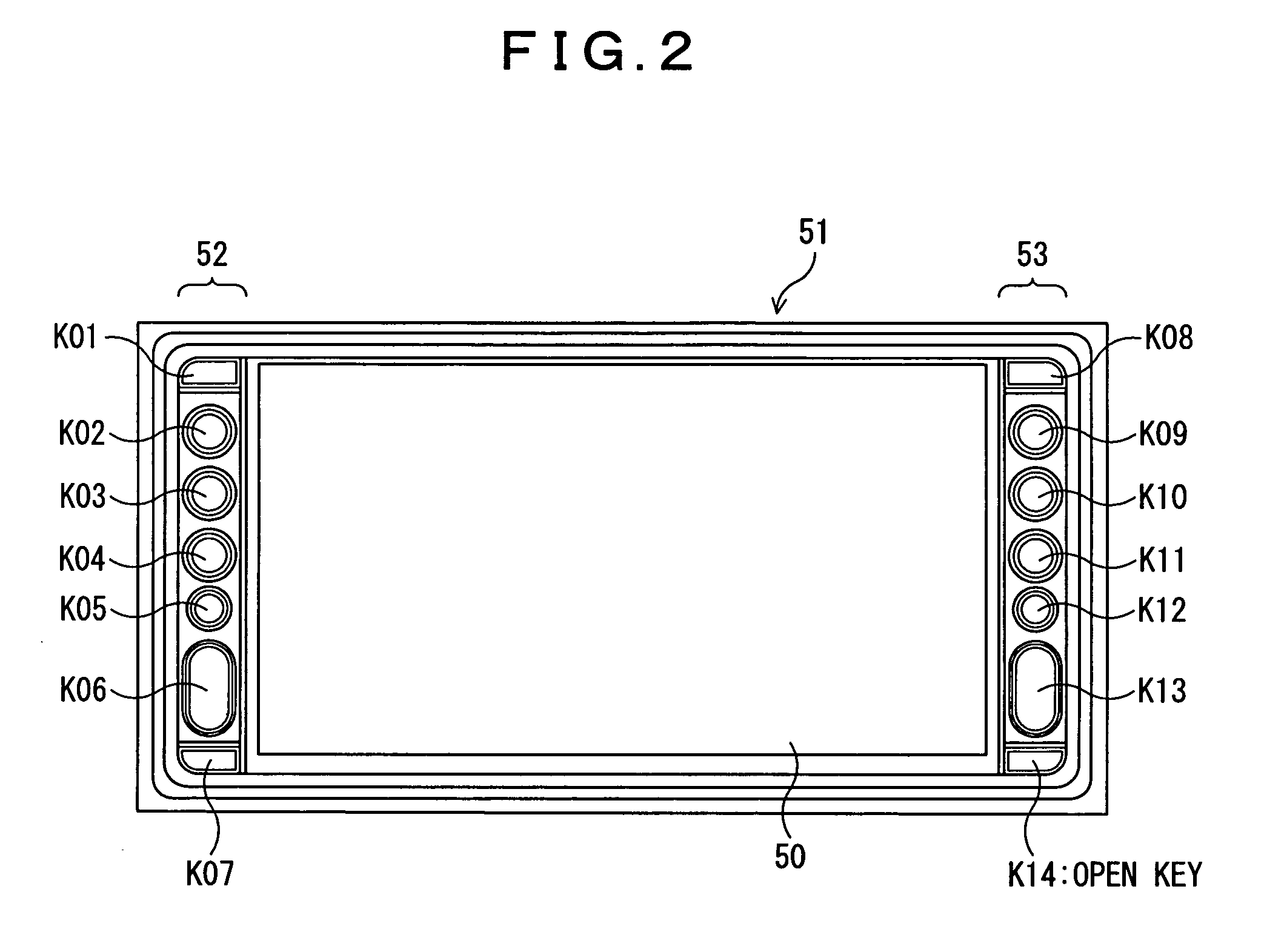
[0042]FIG. 2 is a front view of the operation panel 51, which is composed of the touch panel 50, and key portions 52 and 53 disposed on both sides thereof. The touch panel 50 consists of a liquid crystal display portion and a transparent touch panel portion attached on the display portion. On the liquid crystal display portion, are displayed a navigation map, operation screens for an audio, a television, a-DVD, and the like, characteristic information on FM teletext multiplex broadcasting, and the like. The key portions 52 and 53 are provided with various types of keys K01 to K14, which serve to input commands needed for power-up, mode switching, volume change, station selection, opening of the operation panel, and the like.

[0043] The key K14 is an open key for opening the operation panel 51. Pressing the key opens the operation panel 51 from a closed state shown in FIG. 1A to an opened state shown in FIG. 1B, so that the CD insertion / ejection port 61, the DVD insertion / ejection po...


PUM

PropertyMeasurementUnit
areasaaaaaaaaaa
sizeaaaaaaaaaa
ejection frequencyaaaaaaaaaa

Abstract

An electronic apparatus and a method for ejecting a medium are provided that can ensure identification of eject keys for media even when the display of a touch panel surface is difficult to view. In the electronic apparatus, a touch panel 50 is slid to open a plurality of medium insertion / ejection ports 61 to 63, so that the predetermined medium (CD, DVD, MD) can be inserted therein and ejected therefrom. When the medium insertion / ejection port is opened, a touch panel surface is divided into areas, and the divisional areas SAR1 to SAR3 are allocated to touch switches EJK1 to EJK3 for ejection of the respective predetermined media. When the touch panel surface is touched, it is detected which touch switch is turned on, and then the medium corresponding to the touch switch turned on is ejected.

Description

BACKGROUND OF THE INVENTION [0001] 1. Field of the Invention [0002] The present invention relates to an electronic apparatus and a method for ejecting a medium using the same. More particularly, the invention is directed to an electronic apparatus adapted to expose an insertion / ejection port for a medium to the outside by rotating a touch panel and to insert and eject the medium therein and therefrom, and to a method for ejecting the medium using the same. [0003] 2. Description of the Related Art [0004] Vehicle-mounted multimedia apparatus may incorporate navigation, a radio reception, a television reception, a CD reproduction, an MD (mini disk) reproduction, and a DVD reproduction functions. Such a multimedia apparatus needs to be designed to conform to a predetermined size because it has to be accommodated in a small cabin space. [0005] Minimizing the space taken up by such a multimedia electronic apparatus is often achieved by sharing a display device among the respective functio...

Claims


Application Information

Patent Timeline
Patent Type & Authority Applications(United States)
IPC IPC(8): G11B15/52
CPCG11B17/051G11B17/057G11B33/125G11B33/10G11B33/027
Inventor NAKAMURA, TAKASHISEKINE, SATORU
Owner ALPINE ELECTRONICS INC
Learn More