Coating film tape end structure

Active Publication Date: 2006-01-05
FUJI COPIAN
View PDF0 Cites 6 Cited by
  • Summary
  • Abstract
  • Description
  • Claims
  • Application Information

AI Technical Summary

Benefits of technology

[0007] The principal object of this invention is to provide a coating film end tape structure that prevents the coating film from partly detaching or exfoliating from the base material of the tape, even when a thin coating film tape is used.
[0012] In the end tape structure according to the invention, the winding pressure exerted by outer turns of the tape is not concentrated at the adhered sections described above, even though a thin coating film tape is employed. Therefore, the coating film is prevented from exfoliating from the base material of the coating film tape, accumulation of coating film material at the tip of the transfer head is avoided, the tape unrolls smoothly from the tape supply reel, and neat and uniform transfer of the coating film is achieved.

Problems solved by technology

These conditions cause several problems.
First, they can cause uneven transfer of the coating film onto a receiving surface.
Second, accumulation, at the tip of the transfer head, of coating film adhering to the back of the coating film base material, causes failure of the tip to exert even pressure against the receiving surface.
Third, adhesion of the coating film to the back of an adjacent winding results in resistance to rotation of the reel of transfer tape, making film transfer difficult.
However, when the coating film tape is made thinner in order to miniaturize the coating film transfer tool, the resiliency and tensile strength of the base material of the tape are weakened, and detachment of the coating film can occur easily.
Furthermore, when the diameter of the core is reduced, the winding pressure tends to become concentrated.
Consequently, when a thinner coating film tape is used, the detachment problem becomes more severe.

Method used


Image

  • Coating film tape end structure
  • Coating film tape end structure
  • Coating film tape end structure

Examples


Embodiment Construction

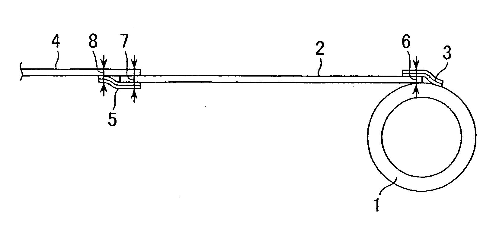
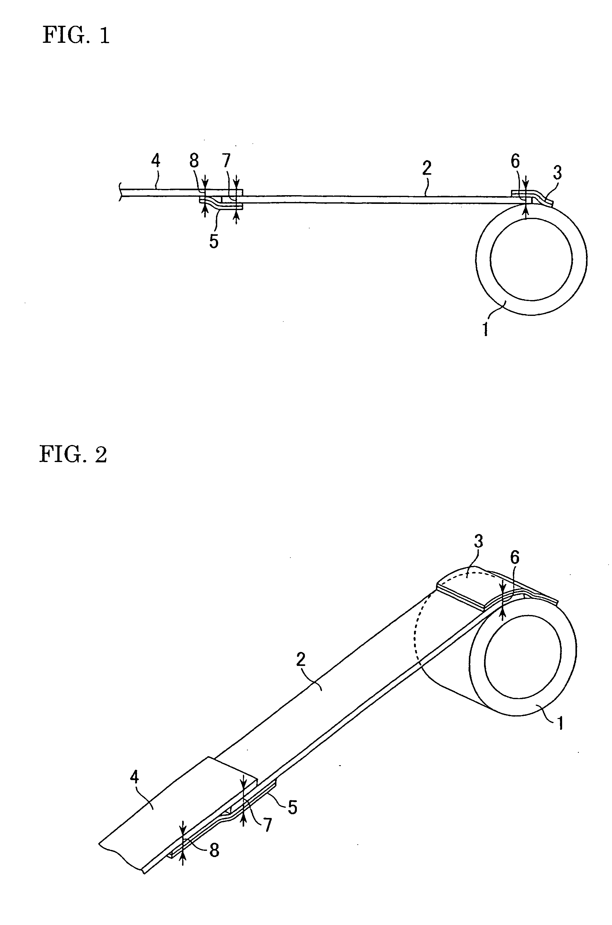
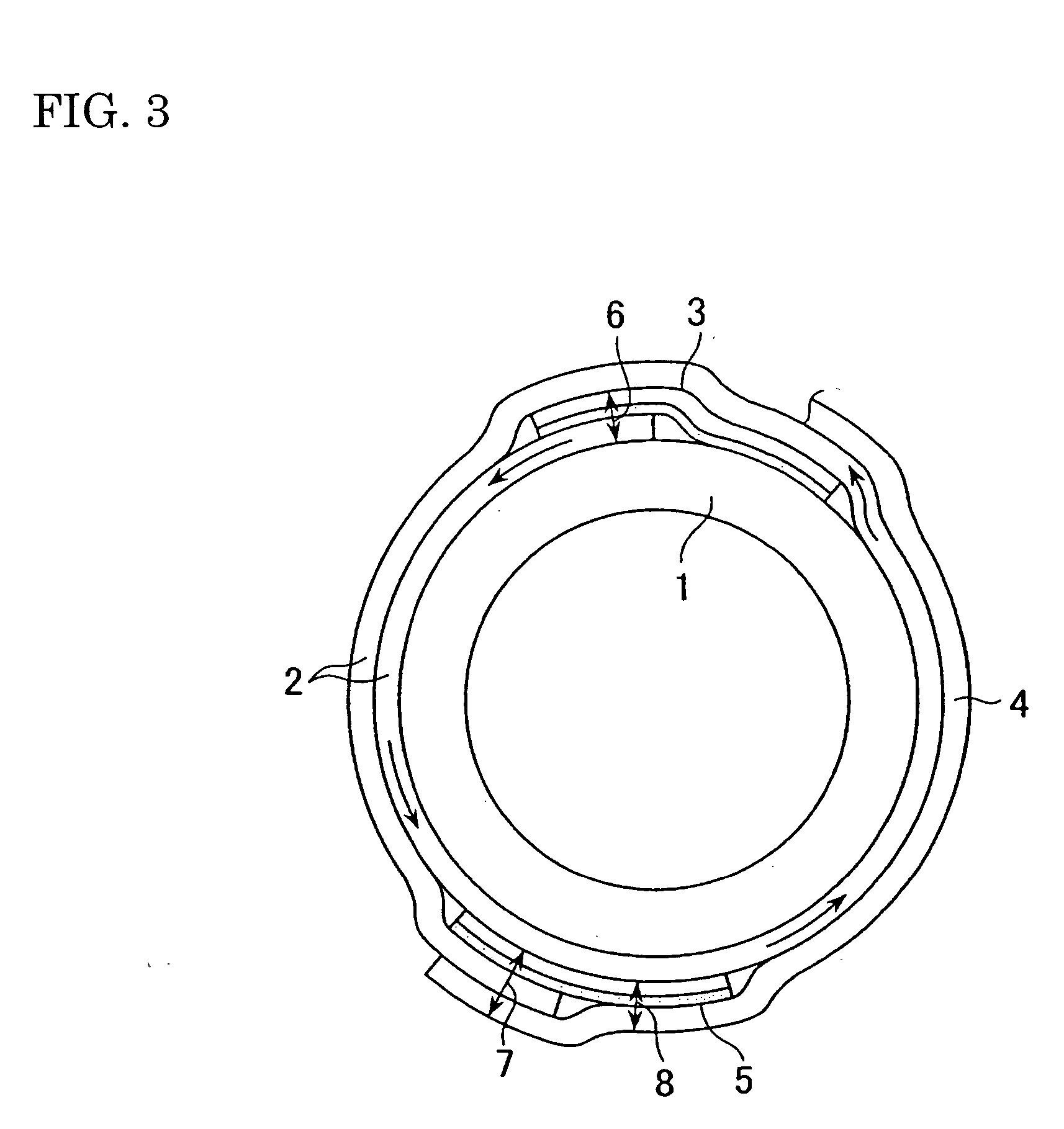
[0016] As shown in FIG. 1, a coating film transfer tape 4 is connected to a core 1 by a length of end tape 2, which has an appearance different from that of the coating film tape. The end tape 2 is connected to the core by a first short length of single-sided adhesive tape 3, a part of which adheres to the outer surface of the core 1, and another part of which overlaps and adheres to the end tape 2 at a location adjacent one end of the end tape 2. The overlapping parts of end tape 2 and adhesive tape 3 constitute a first adhered section having a thickness 6, equal to the sum of the thicknesses of the adhesive tape and the end tape. The other end of the end tape 2 overlaps the coating film tape 4 and is connected to the coating film tape by a second short length of single-sided adhesive tape 5. A part of tape 5 adheres directly to the uncoated side of the base material of the coating film tape 4, and another part of tape 5 adheres to the end tape at the location at which the end tape...


PUM

PropertyMeasurementUnit
Fractionaaaaaaaaaa
Fractionaaaaaaaaaa
Fractionaaaaaaaaaa

Abstract

In a the structure of end tape for revealing impending exhausting of a coating film tape supply, the end tape is connected to the core by a first single-sided adhesive tape, and to the coating film tape by a second single-sided adhesive tape, both adhesive tapes having a thickness of not more than 25μ. The thickness of the second single-sided adhesive tape is 20% to 70% of the total thickness of the adhered section where the second single-sided adhesive tape, the end tape and the coating film tape overlap, and at least 30% of the thickness of the adhered section where the second adhesive tape is adhered directly to the coating film tape. The thickness of the first adhesive tape is 30% to 70% of the total thickness of the adhered section, where the first adhesive tape and the end tape overlap.

Description

FIELD OF THE INVENTION [0001] This invention relates to coating film tapes, and more particularly to the structure of a coating film end tape, that is a short length of tape, having an appearance different from that of a film-coated tape, provided for the purpose of revealing the impending exhaustion of the tape supply. BACKGROUND OF THE INVENTION [0002] A coating film transfer tool is used for transferring a correction film for correction, an adhesive, a decorative coating film, or the like onto a receiving surface. The transfer tool usually employs a coating film tape comprising a layer of coating film layer on a base material. [0003] In order to notify the user when the tape supply in the transfer tool is nearly exhausted, a contrasting length of tape, referred to as an “end tape,” is provided at the end of the coating film tape. The end tape, which is typically composed of a material such as polyester, is connected between a core and the coating film tape. An example of such a s...

Claims


Application Information

Patent Timeline
IPC IPC(8): B32B15/04B32B7/12
CPCB65H37/007B65H2511/114Y10T428/28Y10T428/2848Y10T156/1795Y10T156/1705
Inventor NARIMATSU, KENICHITANAKA, HIDEKI
Owner FUJI COPIAN
Why Eureka
Try Eureka