Radar measurement device and arrangement of a radar measurement device on a container

Pending Publication Date: 2021-04-29
VEGA GRIESHABER GMBH & CO
View PDF5 Cites 0 Cited by
  • Summary
  • Abstract
  • Description
  • Claims
  • Application Information

AI Technical Summary

Benefits of technology

The invention is a radar measurement device with an elastically deformable part that allows it to adapt to uneven surfaces, such as a curved wall. This feature ensures that the device stays securely attached to the wall, preventing it from coming loose or allowing water to enter the space between the device and the wall, which can cause false measurements. This design is useful for radar measurement devices that are attached to flexible walls using adhesive.

Problems solved by technology

The results of the measurement would thus be corrupted, or the measurement would even fail entirely.

Method used


Image

  • Radar measurement device and arrangement of a radar measurement device on a container
  • Radar measurement device and arrangement of a radar measurement device on a container
  • Radar measurement device and arrangement of a radar measurement device on a container

Examples


first embodiment

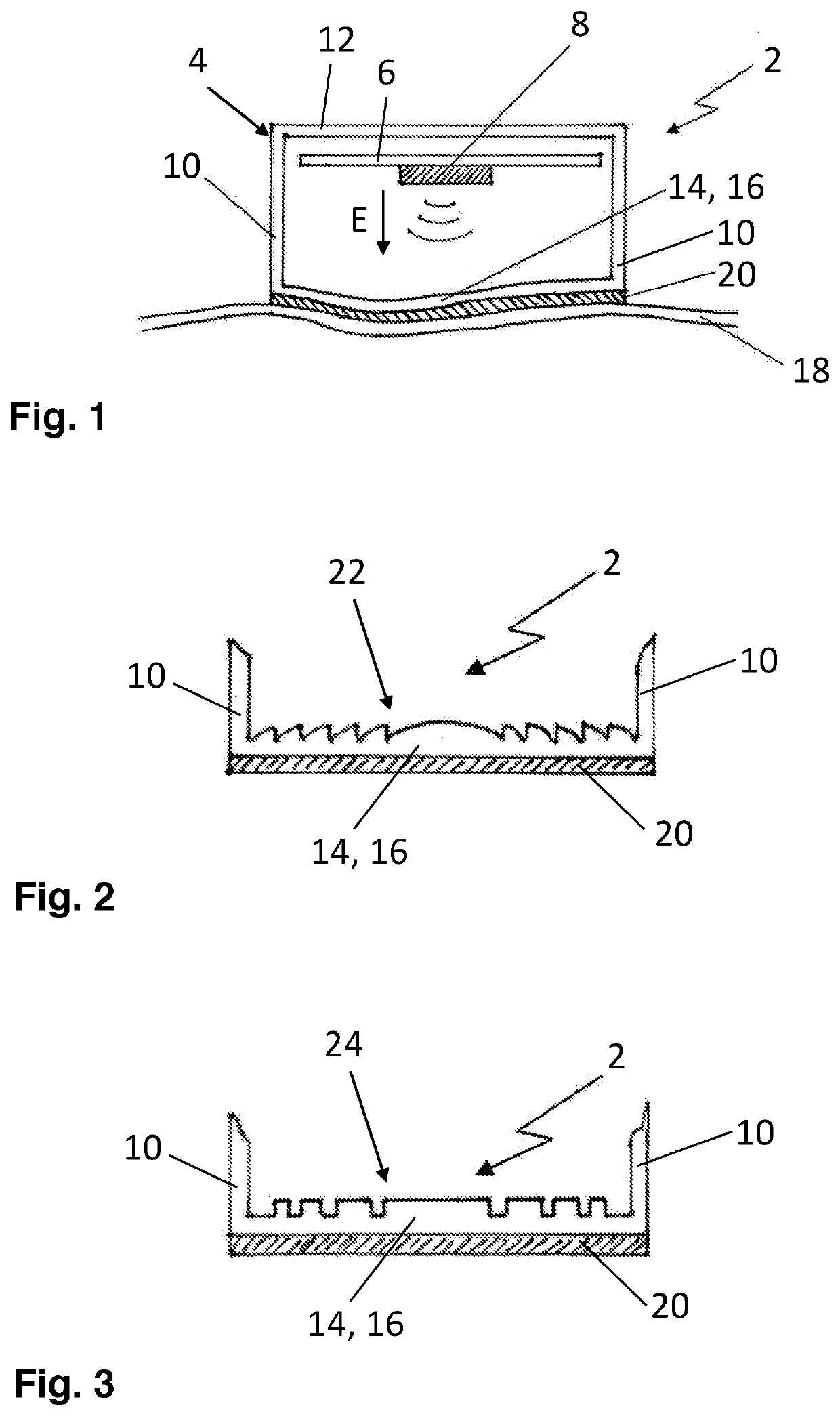
[0049]FIG. 1 shows a radar measurement device 2. In this case, the radar measurement device 2 is a radar fill level measurement device to be arranged on a wall 18 of a container in order to measure the fill level of the contents inside the container (not shown).

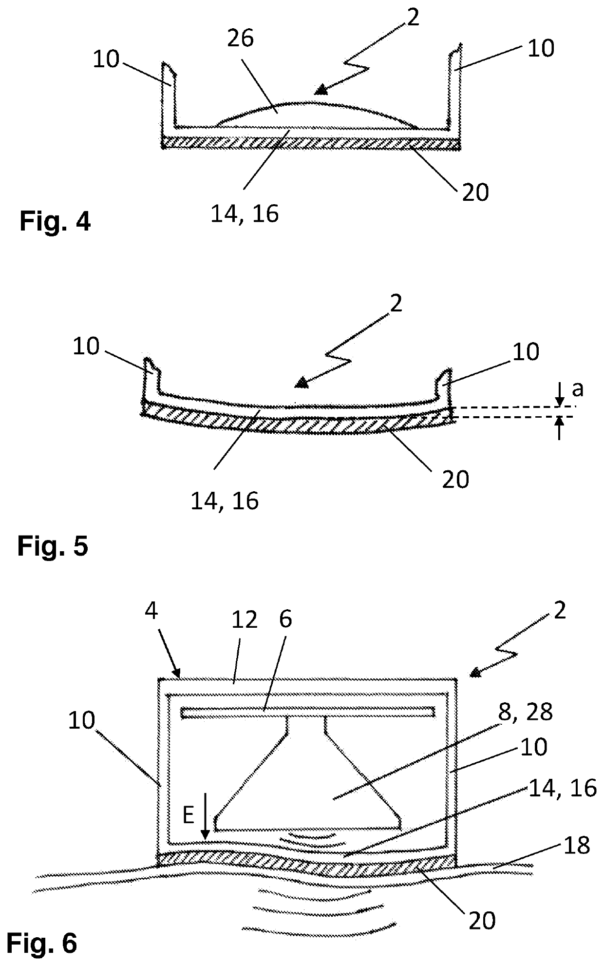
[0050]The radar measurement device 2 is surrounded by a housing 4, the inside of the housing containing a printed circuit board 6 with a transmitter / receiver unit 8 to generate, emit and receive electromagnetic waves. In this embodiment, the transmitter / receiver unit 8 is a radar chip with an integrated primary exciter inside the housing 4. The main emission direction E, extending downwards from the transmitter / receiver unit 8, is shown in FIG. 1. The housing 4 has two deflection resistant side walls 10 and one deflection resistant rear wall 12. The housing 4 further has a portion 14, in this case a housing wall 16 that is elastically deformable and oriented towards the main emission direction E.

[0051]As can be seen in FIG. 1...

seventh embodiment

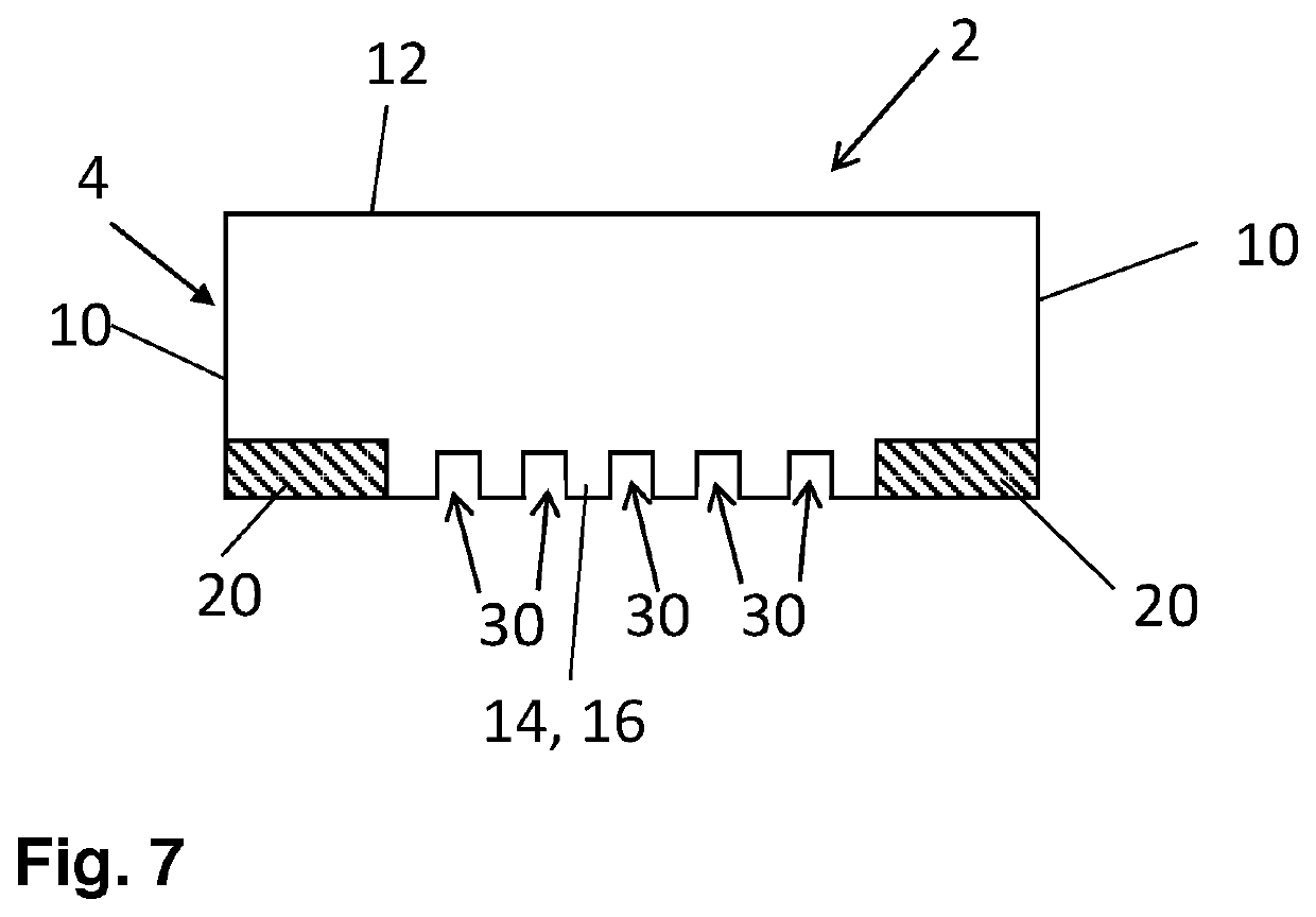
[0061]FIG. 7 shows a radar measurement device 2. Here, the elastically deformable portion 14 is formed by a housing wall 16 with several grooves 30. Furthermore, in this case only a ring-shaped layer of adhesive 20 is applied to the housing 4 to attach the housing 4 to a container.

[0062]It should be noted that specifically the embodiments shown in FIGS. 1 and 6 can also be combined with housing walls 16 according to the embodiments shown in FIGS. 2 to 5 and FIG. 7. Another embodiment is also possible where the housing has rigid walls and is connected with a container via an elastically deformable portion 14 in the form of an elastically deformable compensating element.


PUM


Abstract

A radar measurement device with at least one transmitter to emit electromagnetic waves, the at least one transmitter being arranged inside a housing. The radar measurement device is intended to be securely and lastingly attachable to a flexible wall. For this purpose, at least a portion of the housing has an elastically deformable design. Furthermore, the arrangement of a radar measurement device to a fillable container is described.

Description

CROSS REFERENCE TO RELATED APPLICATIONS[0001]This patent application claims priority to German Patent Application 102019128582.8, filed on Oct. 23, 2019.STATEMENT REGARDING FEDERALLY SPONSORED RESEARCH OR DEVELOPMENT[0002]No federal government funds were used in researching or developing this invention.NAMES OF PARTIES TO A JOINT RESEARCH AGREEMENT[0003]Not applicable.SEQUENCE LISTING INCLUDED AND INCORPORATED BY REFERENCE HEREIN[0004]Not applicable.BACKGROUNDField of the Invention[0005]The invention is a radar measurement device, specifically for fill level measurement, and the arrangement of such device on a container.Background of the Invention[0006]Various embodiments of fill level measuring arrangements to determine and / or monitor the fill level inside a container are known. Radar fill level measurement apparatuses, for example fill level measurement devices which operate according to the transit time principle, emit pulses of electromagnetic radiation at a certain wavelength a...

Claims


Application Information

Patent Timeline
IPC IPC(8): G01F23/284
CPCG01F23/284G01S7/03G01S13/88H01Q1/225H01Q15/08H01Q19/062H01Q1/422H01Q1/427G01S7/027
Inventor WELLE, ROLANDDIETERLE, LEVIN
Owner VEGA GRIESHABER GMBH & CO
Why Eureka
Try Eureka