Rooftop vent for reducing pressure under a membrane roof

a technology of membrane roof and vent, which is applied in the field of rooftop vents, can solve the problems of membrane roof lifted from the subroof, being torn from the building, being damaged in other ways, and being susceptible to damage, so as to achieve the effect of maximizing the area of reduced pressur

Active Publication Date: 2006-01-12
CARLISLE CONSTR MATERIALS LLC
View PDF36 Cites 11 Cited by
  • Summary
  • Abstract
  • Description
  • Claims
  • Application Information

AI Technical Summary

Benefits of technology

[0012] The present invention also includes a membrane roof system having a roof membrane in combination with the present roof vent. In the present membrane roof system, a porous layer or grooves can be provided under the membrane so that air can flow under the membrane. This feature maximizes the area of reduced pressure and helps prevent trapped pockets of air under the membrane.
[0013] Additionally, the present invention includes embodiments where the port is located in the upper dome. In this case, the upper dome and lower dome are connected by a hollow leg. The hollow leg supports the upper dome and provides an air flow path between the lower dome and the port in the upper dome. The port in the upper dome faces downwardly, which tends to prevent water from infiltrating the roof vent.

Problems solved by technology

One problem with membrane roofs is that they are susceptible to damage from high winds.
High winds create a reduced air pressure on the top surface of the membrane, which cause it to lift from the building.
A membrane roof lifted from the subroof can be torn from the building or damaged in other ways.
Hence, one of the challenges of designing membrane roof systems is providing an attachment method strong enough to prevent uplift of the membrane during high wind conditions.
These methods have a tendency to increase heat transmission through the roof, which increases heating and cooling costs.
Also, these methods are not completely reliable in very high winds.
However, both these solutions require air-tight deck assemblies for efficient operation and have a relatively high manufacturing cost.

Method used


Image

  • Rooftop vent for reducing pressure under a membrane roof
  • Rooftop vent for reducing pressure under a membrane roof
  • Rooftop vent for reducing pressure under a membrane roof

Examples


Embodiment Construction

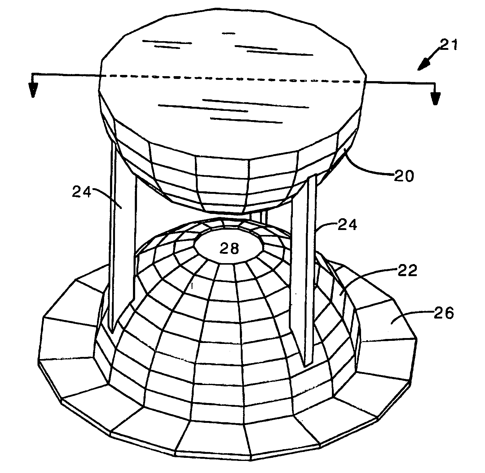
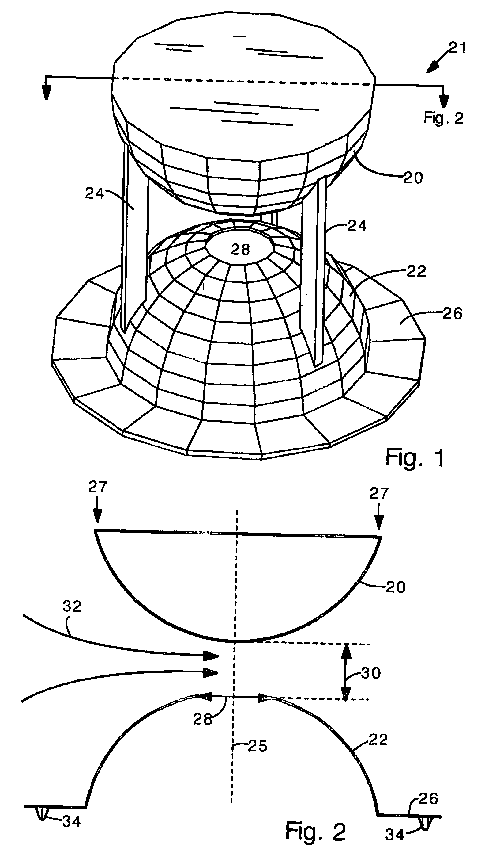
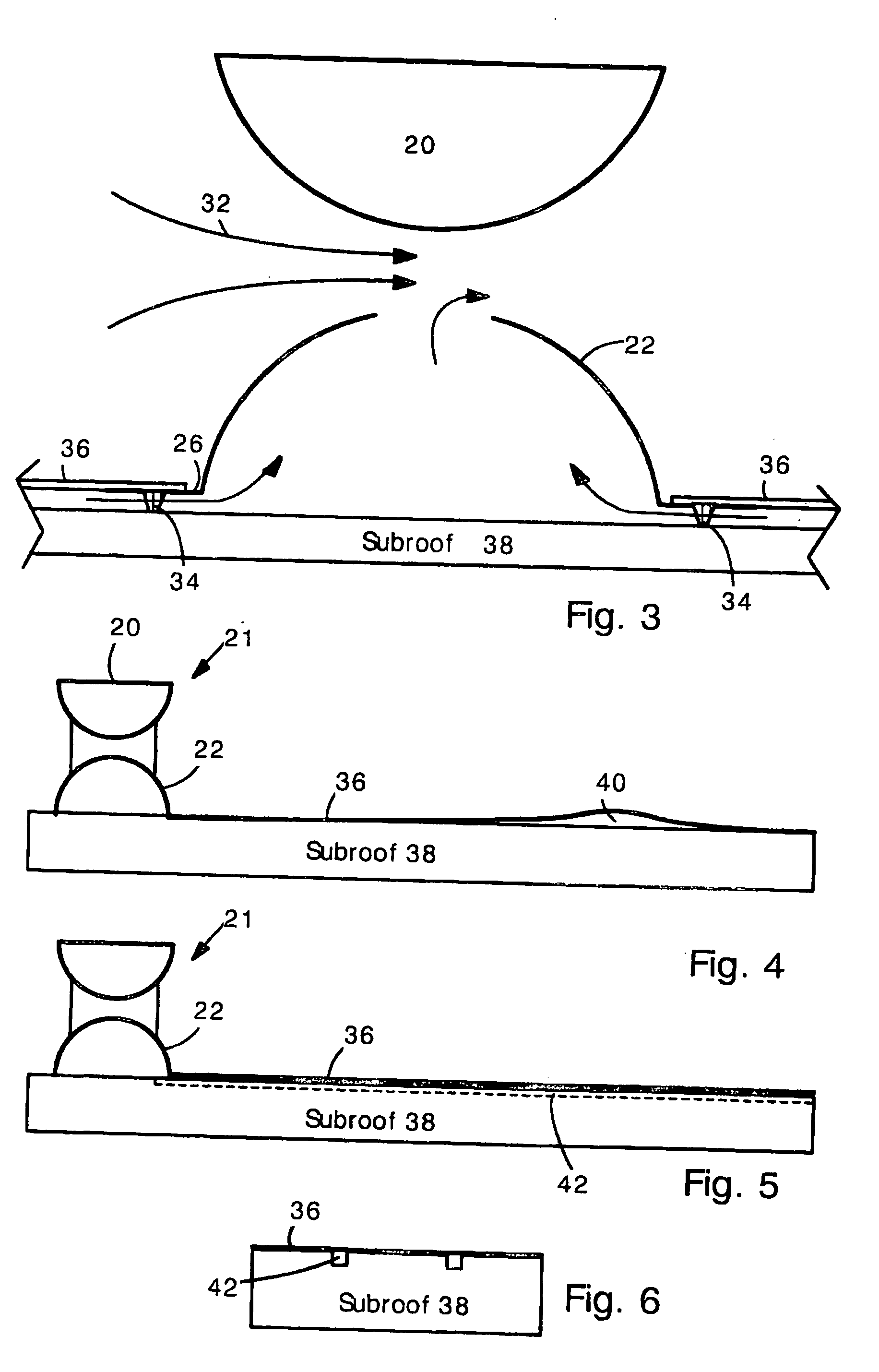
[0025] The present invention provides a roof vent and roof system that reduces air pressure under a membrane roof when wind blows, thereby holding down the membrane roof. The present roof vent employs the Venturi effect to reduce the pressure under the membrane. The reduced pressure tends to prevent uplift during high wind events. Specifically, the present roof vent has two hollow domes separated by a gap. When wind blows, airflow is forced through the gap between the domes where it creates a zone of low pressure due to the Venturi effect. The bottom dome has a port located at the gap. The port is open to the space under the membrane roof. Therefore, when air flows between the two domes, the low pressure at the port tends to draw air from under the membrane and air pressure under the membrane is reduced to less than the atmospheric pressure.

[0026]FIG. 1 shows a perspective view of the present roof vent 21. The roof vent 21 has an upper dome 20, a lower dome 22 and legs 24. Legs 24 ...


PUM


Abstract

Membrane roofs are susceptible to damage in high winds. Wind can lift a membrane roof from a building and cause it to tear or become damaged. The present roof vent prevents liftoff and damage by reducing the air pressure under the membrane during high winds. The present roof vent has two opposed convex domes separated by a gap. Wind blowing across the roof flows between the domes where it accelerates and creates a region of low pressure according to the Venturi effect. The lower dome has an opening at the gap so that the low pressure is applied to the space under the membrane roof. Therefore, when wind blows across the roof, the vent draws air from under the membrane and the membrane is pressed against the roof, preventing liftoff.

Description

CROSS-REFERENCE TO RELATED APPLICATIONS [0001] This application is a continuation-in-part (CIP) of U.S. Ser. No. 10 / 807,412 filed Mar. 24, 2004, and claims priority to U.S. Provisional Patent Application Ser. No. 60 / 466,441 filed Apr. 30, 2003, and the complete contents of each application is herein incorporated by reference.FIELD OF THE INVENTION [0002] The present invention relates generally to rooftop vents, and, more specifically, to a vent for reducing pressure under a membrane roof during windstorms. BACKGROUND OF THE INVENTION [0003] Membrane roof systems are commonly used in low-slope roofs. A membrane roof typically comprises a rubber or plastic (e.g., made of PVC) sheet that provides a moisture and vapor barrier. Membrane roofs are relatively inexpensive to install and consequently the use of membrane roof systems has been expanding in recent years. [0004] One problem with membrane roofs is that they are susceptible to damage from high winds. High winds create a reduced ai...

Claims


Application Information

Patent Timeline
Patent Type & Authority Applications(United States)
IPC IPC(8): E04B7/00E04H12/28E04D5/14E04D13/17
CPCE04D13/17E04D5/14
Inventor JONES, JAMES R.TELIONIS, DEMETRIVLACHOS, PAVLOSGRANT, ELIZABETHRULLAN, JOSEJOHNSON, CHARLES S.
Owner CARLISLE CONSTR MATERIALS LLC
Why Eureka
Try Eureka