This helps you quickly interpret patents by identifying the three key elements:
Problems solved by technology
Method used
Benefits of technology
Problems solved by technology
In other words, electric energy generated in the dynamic braking mode is typically wasted.
As indicated above, prior art locomotives typically waste the energy generated from dynamic braking.
Attempts to make productive use of such energy have been unsatisfactory.
Such systems are not suited for recovering energy to propel the locomotive itself.
Among the disadvantages of such a system are the safe storage of the hydrogen gas and the need to carry water for the electrolysis process.
Still other prior art systems fail to recapture the dynamic brak
Method used
Image
Click on the blue label to locate the original text in one second.
Reading with bidirectional positioning of images and text.
Examples
Embodiment Construction
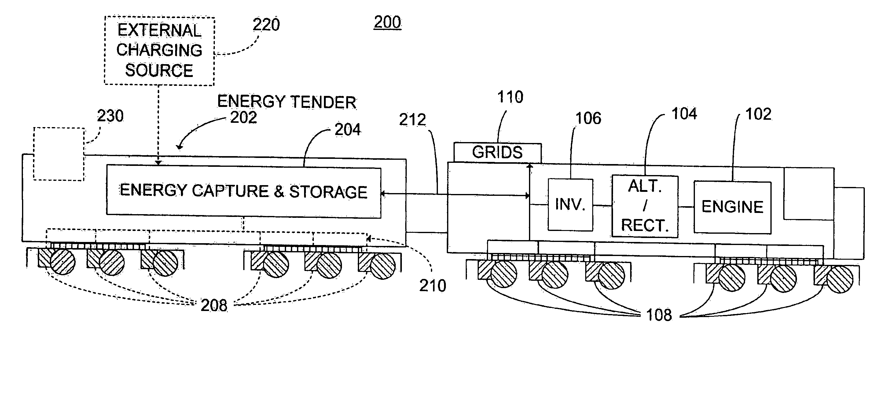
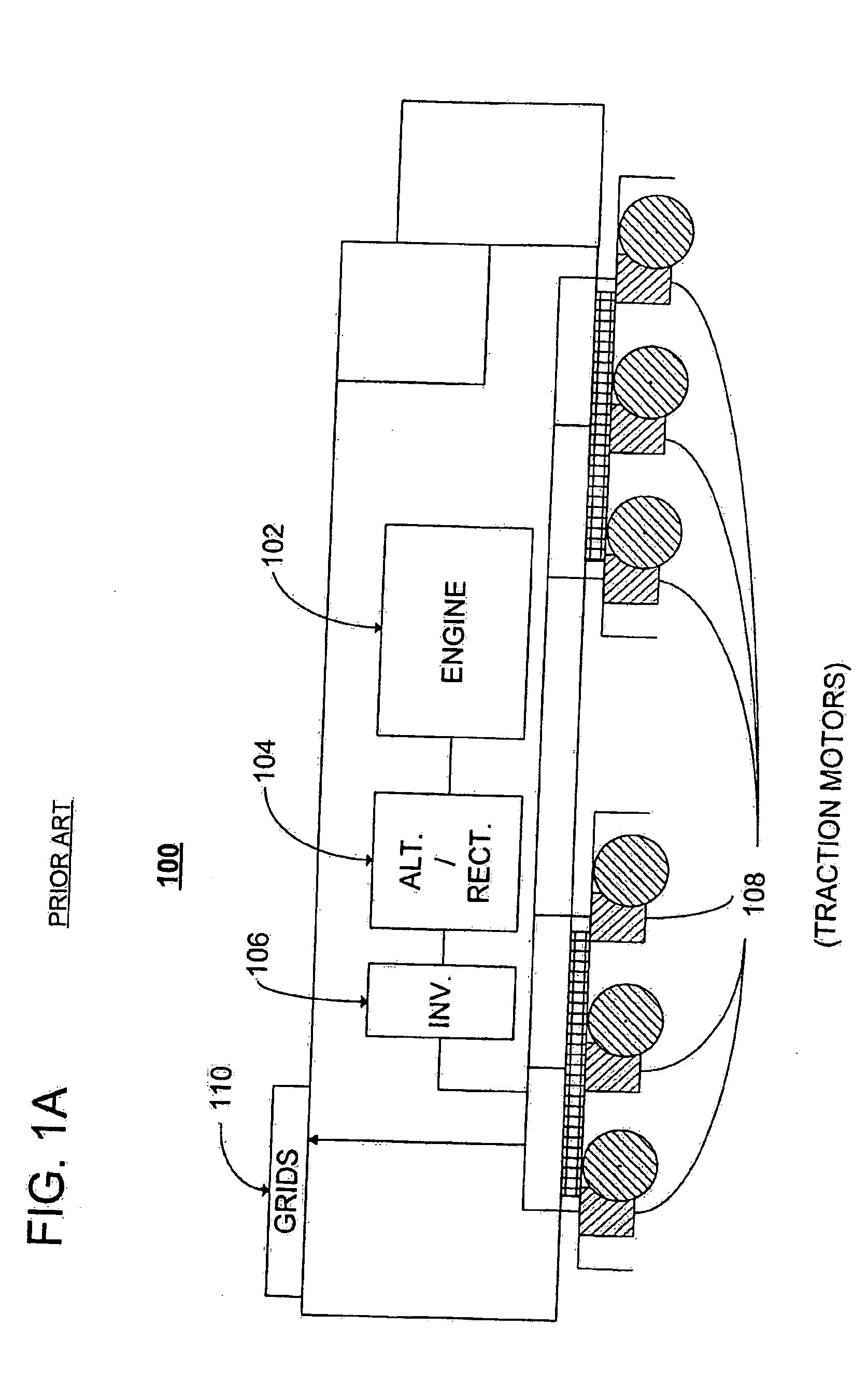
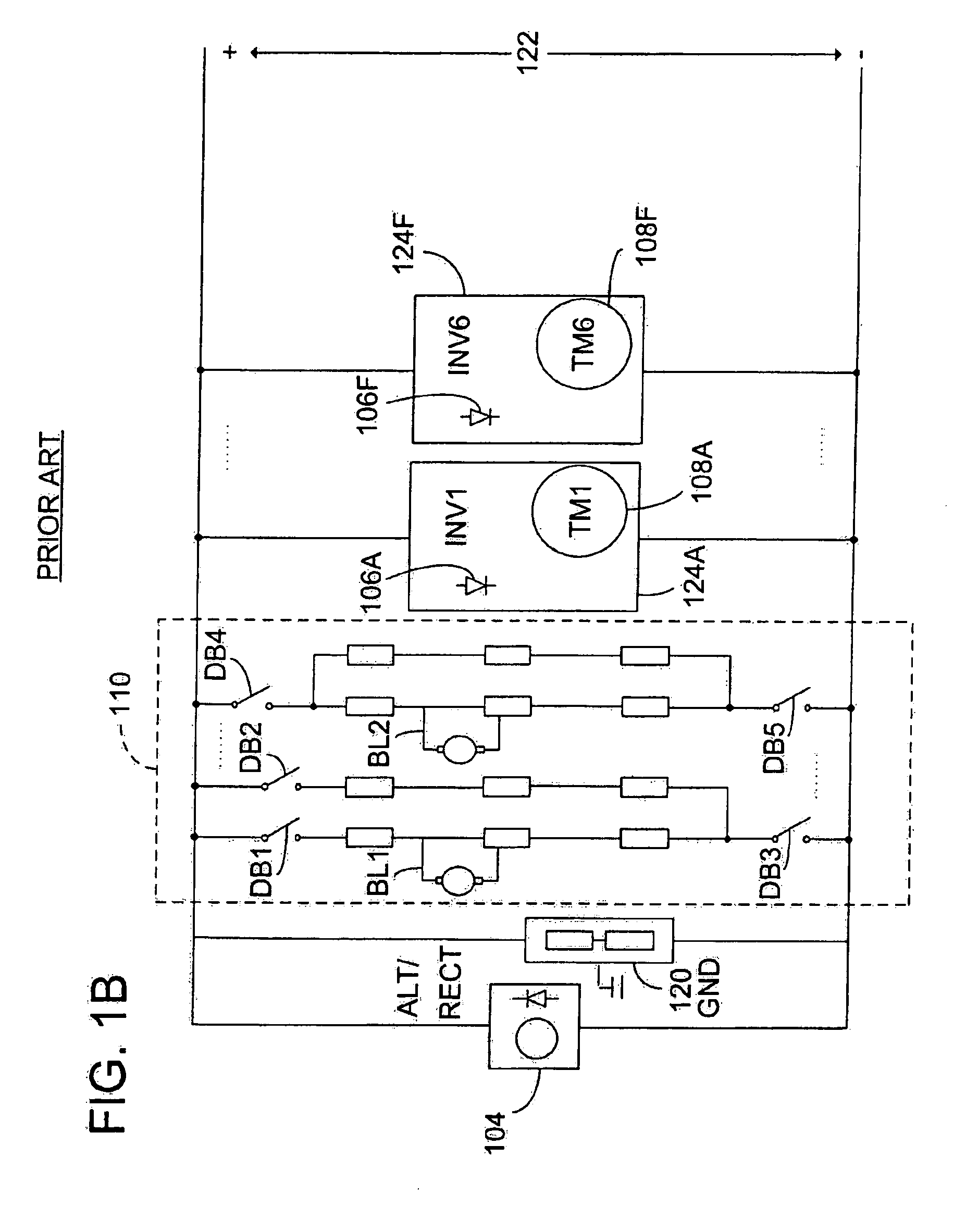
[0039] The art of hybrid locomotive energy systems has advanced through the inventions described in previously filed applications in this chain of patent applications. These focused on locomotives and tender cars that advantageously include the capacity to generate electrical power from a dynamic braking operating mode, to store such power, and to use such power at a later time during a motoring operating mode. Systems in such previously filed applications generally referred to components of a single hybrid energy railroad vehicle. The present application focuses on a class of multipurpose regenerative energy railway vehicles that is for carrying freight as one of its primary functions, and that also, through the components described herein, has power generation capability. Such railroad vehicles comprise a drive unit, such as a traction motor, operable in three movement-type operating modes: coasting; dynamic braking; and motoring. In some embodiments of such railroad vehicles, a p...
PUM
Abstract
A railroad vehicle (1500) for carrying freight is described. The railroad vehicle (1500) comprises power regeneration capability through a traction motor (1530) linked to a driving wheel (1520D), an electrical energy storage system (1550), a controller (1570) that may selectively operate the traction motor (1530) in a motoring mode, a coasting mode, or a dynamic braking mode. In the dynamic braking mode electrical energy from the traction motor (1530) is transmitted to the electrical energy storage system (1550). The controller (1570) is in communication with a communication link (1580) that receives control commands from an external control source (1595), and those control commands indicate the operating mode for a particular period of time.
Description
CROSS REFERENCE TO RELATED APPLICATIONS [0001] The invention of the present application is a continuation-in-part of U.S. patent application Ser. No. 10 / 435,261, filed May 9, 2003, entitled Multimode Hybrid Energy Railway Vehicle System and Method, which is a continuation-in-part of U.S. patent application Ser. No. 10 / 032,714, filed on Dec. 26, 2001, entitled Locomotive Energy Tender, now U.S. Pat. No. 6,612,245 (issued Sep. 2, 2003), which claims priority based on U.S. Provisional Application Ser. No. 60 / 278,975, filed on Mar. 27, 2001, the entire disclosures of which are incorporated herein by reference. [0002] The following commonly owned, co-pending applications are related to the present application and are incorporated herein by reference: [0003] U.S. patent application Ser. No. 10 / 033,172, filed on Dec. 26, 2001, and entitled “HYBRID ENERGY POWER MANAGEMENT SYSTEM AND METHOD”; [0004] U.S. patent application Ser. No. 10 / 033,347, filed on Dec. 26, 2001, and entitled “HYBRID ENE...
Claims
Application Information
Patent Timeline
Application Date:The date an application was filed.
Publication Date:The date a patent or application was officially published.
First Publication Date:The earliest publication date of a patent with the same application number.
Issue Date:Publication date of the patent grant document.
PCT Entry Date:The Entry date of PCT National Phase.
Estimated Expiry Date:The statutory expiry date of a patent right according to the Patent Law, and it is the longest term of protection that the patent right can achieve without the termination of the patent right due to other reasons(Term extension factor has been taken into account ).
Invalid Date:Actual expiry date is based on effective date or publication date of legal transaction data of invalid patent.