Air and water hose apparatus for firefighters

Inactive Publication Date: 2006-01-12
1005 LLC
View PDF12 Cites 9 Cited by
  • Summary
  • Abstract
  • Description
  • Claims
  • Application Information

AI Technical Summary

Benefits of technology

[0016] The present invention is an air and water hose apparatus to be used in an air and water supply system to deliver water and air to the firefighter at all times. The hose apparatus reduces the need for firefighters to rely on the limited amount of air supplied by their tanks when they are trapped in a structure or fighting a fire. The present invention includes at least one air hose extending along the length of a water hose. Adaptors are provided at each end of the air and water hoses to form the hose apparatus. An outer cover can be provided around the air hose and water hose to connect the air hose and water hose together in a single hose. The adaptors have an inner passageway into which the end of the water hose is mounted. The end of the inner passageway of the first adaptor opposite the hose apparatus is connected to the water supply and acts as a water inlet. The end of the inner passageway of the second adaptor has a nozzle and acts as a water outlet. The inner passageway has an air groove which extends around the inner surface of the inner passageway. The inner passageway also has seals which form an air tight air passageway between the water hose and the air groove. The adaptors have a first air hole which is in fluid communication with the air hose and the air groove. The adaptors also have a second air hole in fluid communication with the air groove. In the first adaptor, the second air hole is connected to the air supply and acts as an air inlet. In the second adaptor, the breathing hose of a firefighter is connected to the second air hole and the second air hole acts as an air outlet. A coupling having a one-way valve can be connected to the second air hole. When the air supply or the breathing hose is connected to the coupling, air can flow into or out of the air hose through the second air hole and the coupling. When the air supply or the breathing hose is disconnected from the coupling, the valve is closed preventing air from entering or exiting the air hose. A pressure regulating device can be positioned between the air supply and the second air hole on the first adaptor. In one (1) embodiment, the hose apparatus is only a single section of the overall water hose of the fire hose. This ensures that no part of the air hose extends outside the hose apparatus and is exposed to possible damage.

Problems solved by technology

One of the dangers that firefighters face is being trapped or lost in the structure which is on fire.
One of the main reasons that firefighters die in such a situation is that they run out of air.
Most of these tanks, due to their size and weight, have very limited air supply.
Thus, if a firefighter is trapped for an extensive period of time, the supply is eventually exhausted which usually results in the death of the firefighter.
This design exposes the air tube to possible damage which could stop the flow of air through the tube.
This system could not be used in conjunction with the compressed air systems currently used by firefighters.
The small size of the inner diameter of the air hose would not allow enough air at atmospheric pressure to travel through the air hose to support the firefighter.
One of the disadvantages of this system is that the flow of air depends on the flow of water.
In addition, as with the apparatus of the Loomis reference, the positioning of the air tube on the outside of the water hose exposes the air tube to possible damage which could stop the flow of air through the tube.
In current systems using high pressure, compressed air, air which leaks from a damaged air tube could potentially feed the fire.
However, this system is very unreliable.
This system is difficult to use.
However, a more substantial disadvantage of this system is that the water must be turned off before air can be supplied.
Further, this system uses air at low pressures and can only be used as an emergency system.
However, this air line is exposed and therefore is not intended to be used by a firefighter in a burning structure.

Method used


Image

  • Air and water hose apparatus for firefighters
  • Air and water hose apparatus for firefighters
  • Air and water hose apparatus for firefighters

Examples


Embodiment Construction

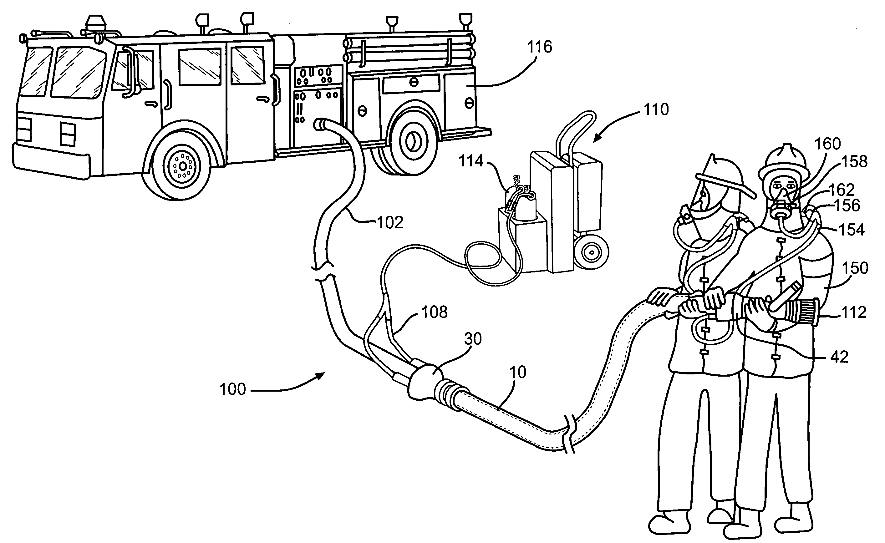
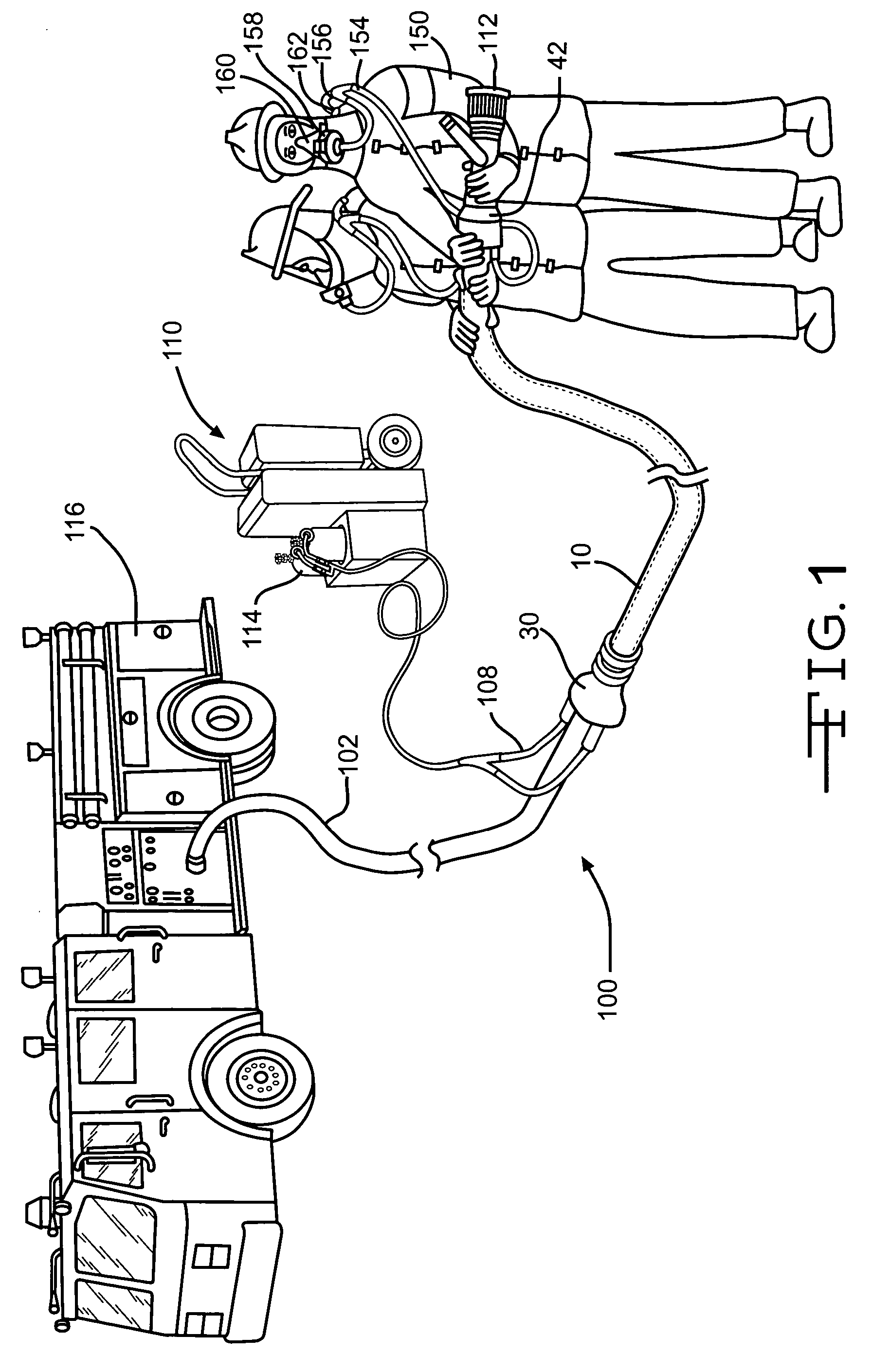
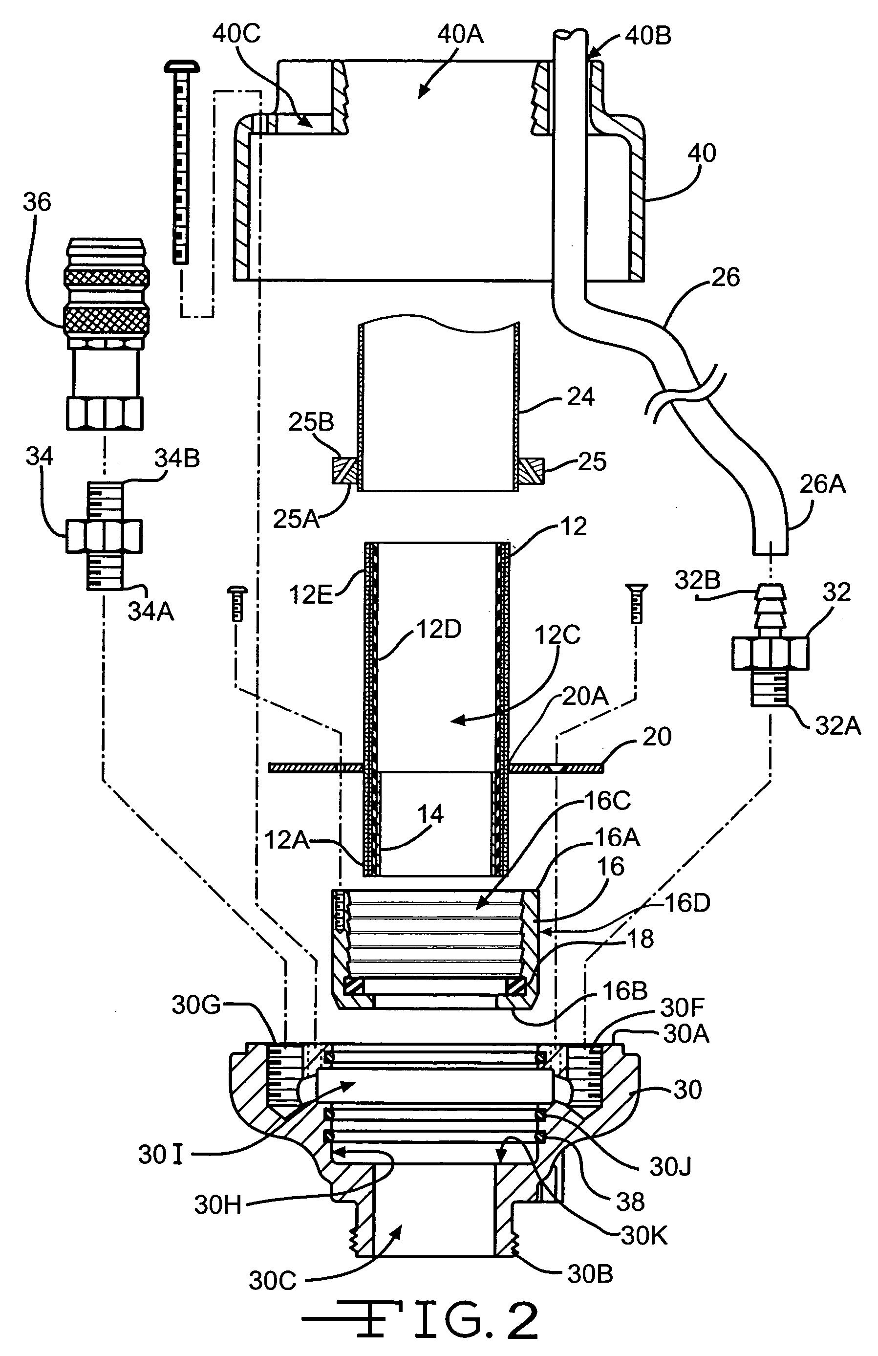
[0028] The air and water hose apparatus 10 of the present invention includes a water hose 12 and an air hose 26 extending between a pair of adaptors 30 and 42. In one (1) embodiment, the hose apparatus 10 is used in an air and water supply system 100 to provide water and air or other breathable gases to firefighters 150 (FIG. 1). The air and water supply system 100 includes the hose apparatus 10 connected at one (1) end to an air supply 110 and water supply and connected at the other end to breathing hose 154 for a firefighter 150. In one (1) embodiment, the breathing hose 154 is connected to a self-contained breathing apparatus (SCBA) used by the firefighters 150. Applicant's co-pending U.S. patent application Ser. No. 10 / 359,799 describes an air and water hose apparatus which includes a water hose and an air hose which can be used as part of an air and water supply system, the application is incorporated herein by reference in its entirety.

[0029] In one (1) embodiment, the air su...


PUM


Abstract

A hose apparatus used as part of an air and water supply system to deliver water and air to a firefighter. The hose apparatus includes an air hose and a water hose with an adaptor at each end of the air and water hoses. The adaptors have an inner passageway with an air groove. The adaptors have a first air hole in fluid communication with the air hose and the air groove and a second air hole in fluid communication with the air groove and the air supply or breathing hose for the firefighter. The second air hole has a coupling which prevents air from exiting the adaptors when the hose apparatus is not in use.

Description

CROSS-REFERENCE TO RELATED APPLICATIONS [0001] This application is a continuation-in-part of application Ser. No. 10 / 359,799 filed Feb. 6, 2003, which is a continuation-in-part of application Ser. No. 09 / 802,597 filed Mar. 9, 2001, now U.S. Pat. No. 6,520,178.STATEMENT REGARDING FEDERALLY SPONSORED RESEARCH OR DEVELOPMENT [0002] Not Applicable BACKGROUND OF THE INVENTION [0003] (1) Field of the Invention [0004] The present invention relates to an air and water hose apparatus and the method of using the air and water hose apparatus to supply air and water to firefighters during a fire. In particular, the present invention relates to a hose apparatus which has air and water hoses and which has adaptors mounted on each end of the air and water hoses which enable air and water to be provided to a firefighter. [0005] (2) Description of the Related Art [0006] One of the dangers that firefighters face is being trapped or lost in the structure which is on fire. One of the main reasons that ...

Claims


Application Information

Patent Timeline
IPC IPC(8): A62C35/00
CPCA62C33/00A62B7/12Y10T137/6918
Inventor BAKER, FRED E.BADGETT, ROGER
Owner 1005 LLC
Why Eureka
Try Eureka