
Intrusion barrier and thermal insulator for thermostat

a technology of intrusion barrier and thermal insulation, which is applied in the direction of heating types, electric apparatus casings/cabinets/drawers, instruments, etc., can solve the problems of inability to accurately control room temperature, and inability to accurately control the thermosta

Inactive Publication Date: 2006-01-12
INT CONTROLS & MEASUREMENT
View PDF10 Cites 103 Cited by
  • Summary
  • Abstract
  • Description
  • Claims
  • Application Information

AI Technical Summary

Benefits of technology

[0006] It is another object to provide an effective solution to the above-mentioned problem, which solution is of a straightforward, one-piece design, and which is simple to install.
[0007] It is a more specific object to provide a barrier that diverts or blocks intrusion air from entering the thermostat or other similar control device.
[0011] In either case, any intrusion air ends up being mixed in with the room air, and does not pass directly into the thermostat, and the thermostat is held out of direct thermal contact with the wall itself, which may not necessarily be at the same temperature as the room air. The thermostat then senses the room air parameters, e.g., temperature or humidity, much more accurately, and permits the furnace, air conditioner, heat pump, or other environmental control equipment to keep the interior room air within the comfort range that is set on the device.

Problems solved by technology

Even if a contractor plasters or caulks the wire opening during construction of the house, the plaster or caulk can eventually dry and crack, and permit intrusion air to enter the thermostat.
In addition, accurate control over room temperature is made difficult when the thermostat housing is in direct contact with the wall, which may be significantly warmer or cooler than the room air.
That is, if the thermostat is in direct thermal contact with the wall, and if the wall is warmer or cooler than the air in the room, the accuracy of the thermostat can be impaired, even in the absence of intrusion air from the wall cavity.
However, no one to date has considered thermally isolating the thermostat from the surface of the wall.

Method used


Image

  • Intrusion barrier and thermal insulator for thermostat
  • Intrusion barrier and thermal insulator for thermostat
  • Intrusion barrier and thermal insulator for thermostat

Examples


Embodiment Construction

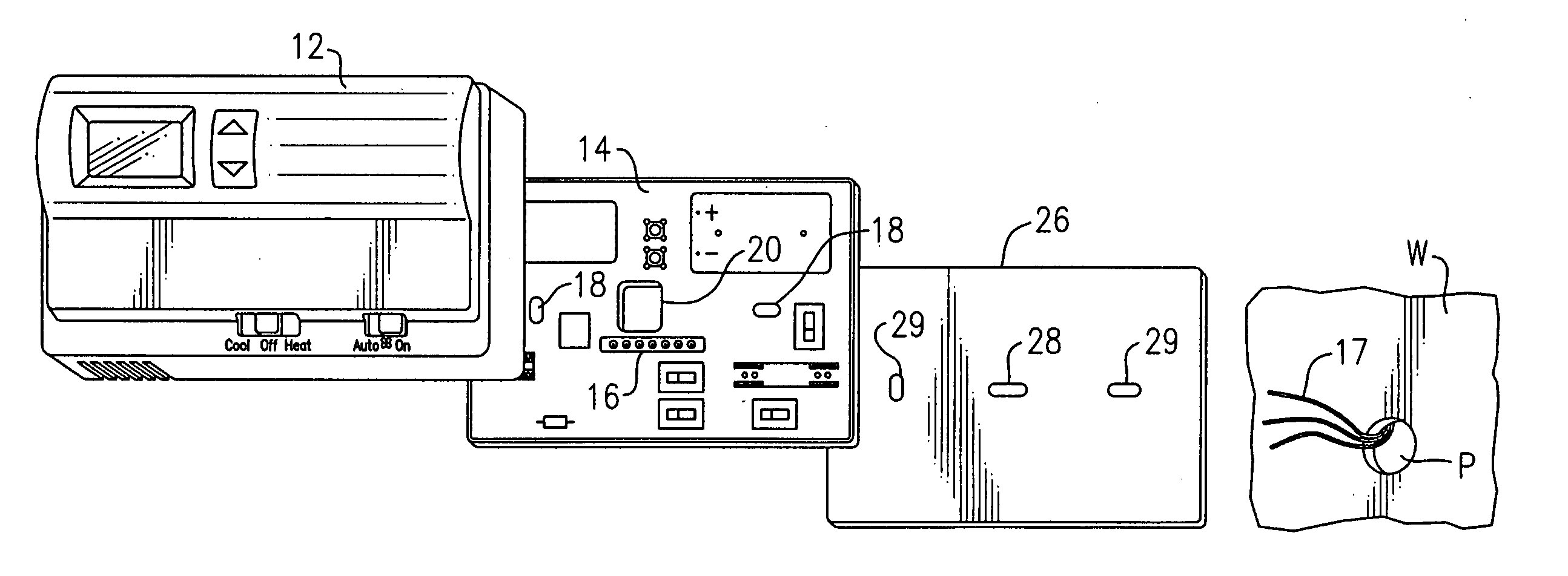
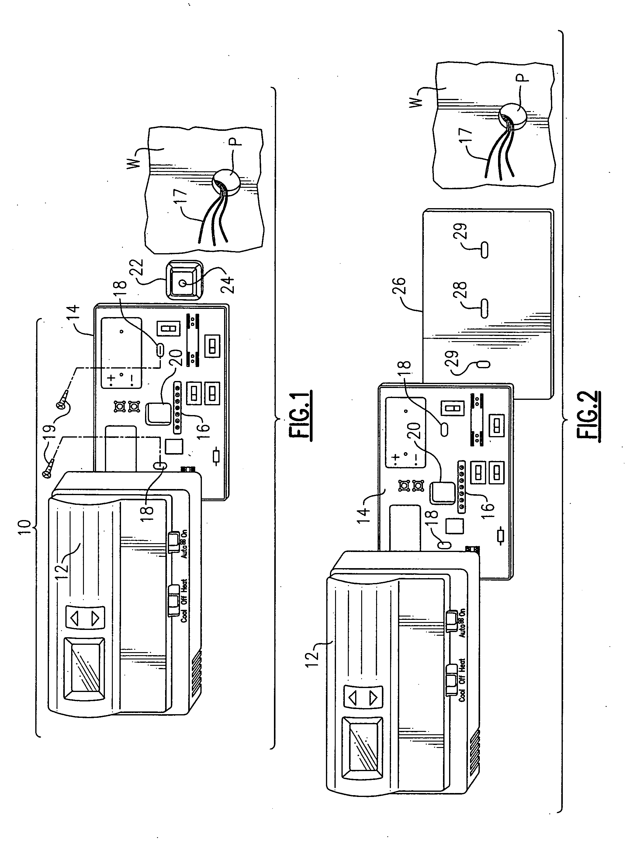
[0019] With reference now to the Drawing, FIG. 1 shows a wall thermostat assembly 10 that is to be mounted onto a wall W of a room of a dwelling, commercial building, or other structure where a human comfort space is to be maintained within some desired range of temperature. Here the thermostat 10 comprises a front cover 12 which fits onto a back plate 14. There are sensors, switches, and electrical and electronic components mounted on the back plate 14, which elements are of any well known configuration, and are not shown in detail and not discussed here, except that a contact strip 16 is present for connecting some number of thermostat wires 17, here shown protruding out a hole or penetration P in the wall W. In this thermostat 10, there are screw holes 18 provided at the left and right sides of the back plate 14, and a pair of threaded fasteners 19 that mount the back plate 14 onto the wall W. The back plate is positioned on the wall so that a thermostat wire opening 20, which is...


PUM


Abstract

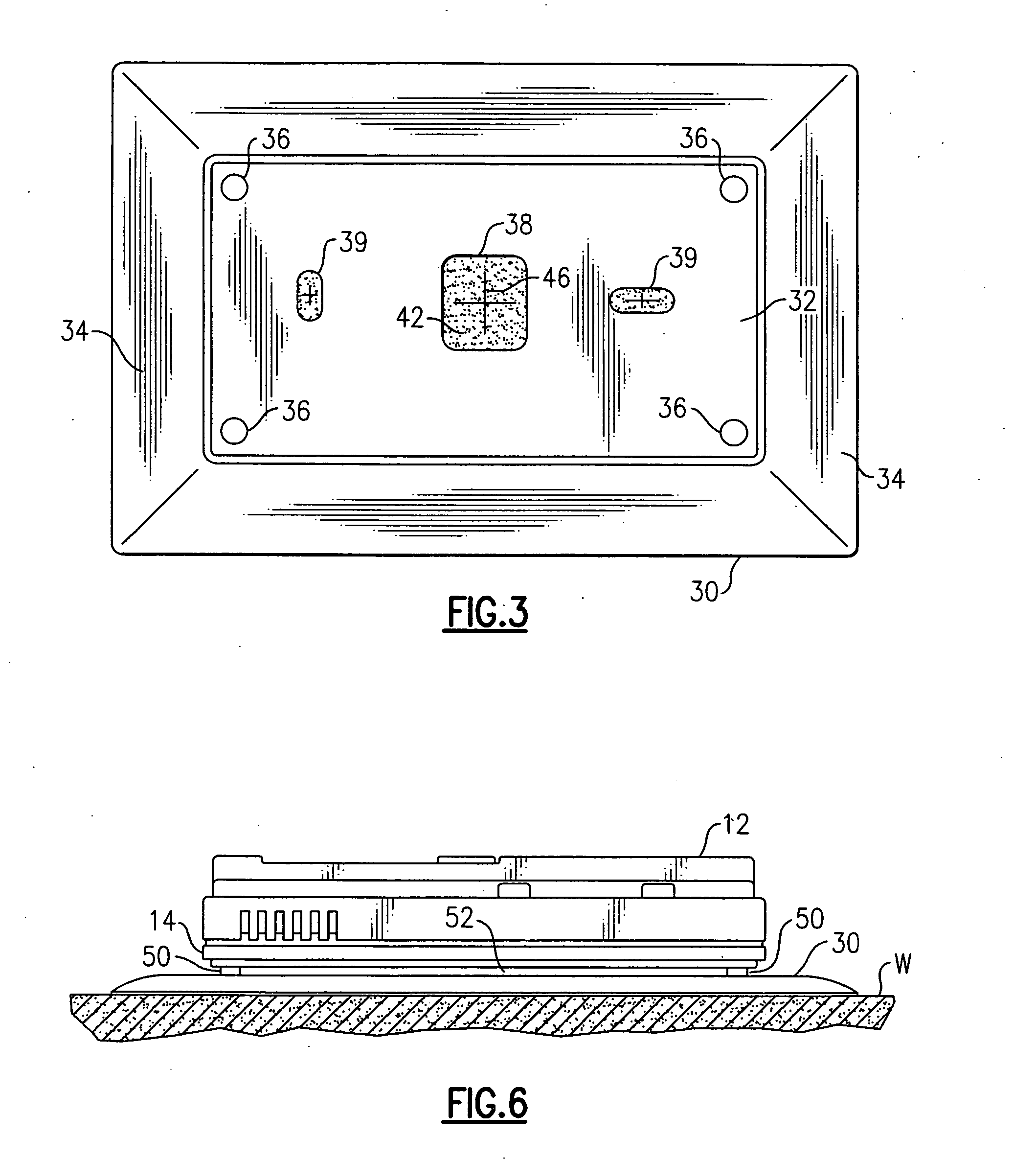
A wall plate for a wall thermostat blocks intrusion air from the thermostat. The wall plate has a wire passage aligned with the wall penetration through which the thermostat wires emerge. The wall plate member directs any intrusion air that flows out the penetration away from the cavity of said thermostat. An insulating layer, e.g., a closed-cell foam sheet, in the wall plate insulates the thermostat from direct thermal contact with the wall. The closed-cell material closes around the thermostat wires. Bosses or feet on the thermostat back plate create a standoff between the wall plate and the thermostat.

Description

BACKGROUND OF THE INVENTION [0001] This invention relates to control devices for controlling the temperature, humidity, and / or other environmental conditions in an interior comfort space, and is more particularly concerned with an improvement to a wall thermostat to prevent inaccuracies and misoperation that may result from intrusion air which may enter the thermostat from a hollow wall on which the thermostat is mounted. [0002] Wall thermostats are typically installed on an interior wall of a house or other building to control the operation of a furnace, air conditioner, heat pump, or other environmental control equipment. The thermostat is intended to monitor the temperature of the room or other interior comfort space continuously, and to adjust the operation of the associated environmental control equipment to keep the interior comfort space parameter (e.g., temperature) within some range (e.g., 68° F., ±1.0° F.). Other controls may be sensitive to other parameters, such as humid...

Claims


Application Information

Patent Timeline
Patent Type & Authority Applications(United States)
IPC IPC(8): G05D23/00
CPCF23N2025/12H05K5/0247G05D23/1902Y10S236/19F23N2225/12
Inventor MORROW, BENJAMIN V.KADAH, RONALD B.
Owner INT CONTROLS & MEASUREMENT
Learn More