Multi-protocol or multi-command RFID system

Active Publication Date: 2006-01-12
TRANSCORE BERMUDA LICENSE
View PDF30 Cites 136 Cited by
  • Summary
  • Abstract
  • Description
  • Claims
  • Application Information

AI Technical Summary

Benefits of technology

[0010] It is therefore one object of the present invention to provide an interrogating system that is able to simultaneously operate a plurality of closely-spaced interrogators. It is another object of the invention to provide an interrogating system that synchronizes a plurality of interrogators. It is another object of the invention to provide a system that simultaneously processes different protocols used to communicate with tags. It is another object of the invention to provide a system that simultaneously processes different backscatter protocols. It is yet another object of the invention to provide a system that simultaneously processes different active and backscatter protocols. It is yet another object of the invention to provide an interrogating system that avoids interference on an uplink by a downlink, as well as downlink on downlink interference, and uplink on uplink interference. It is yet another object of the invention to provide a self-test operation that can verify operation of the interrogator and that does not have the time constraints of the check tag. It is another object of the invention to provide an interrogation system in which uplink signals are received, and downlink signals are sent, over a single antenna.
[0011] In accordance with these and other objects of the invention, a multi-protocol RFID interrogating system is provided that employs a synchronization technique (step-lock) for a backscatter RFID system that allows simultaneous operation of closely spaced interrogators. The interrogator can read both active and backscatter tags more efficiently when combined with time division multiplexing. The multi-protocol RFID interrogating system can communicate with backscatter transponders having different output protocols and with active transponders, including: Title 21 compliant RFID backscatter transponders; IT2000 RFID backscatter transponders that provide an extended mode capability beyond Title 21;

Problems solved by technology

This introduces new challenges, particularly when a system is designed to communicate with tags of differing protocols, requiring performance sacrifices.
However, the ability to operate with acceptable performance is limited by the ability of the interrogator to reject adjacent channel interference, and in the case where frequencies are re-used, co-channel interference.
In addition, the interference impact of operating multiple interrogators in close proximity to one another is complicated by second and third order inter-modulation effects.
That, however, results in lower speed

Method used


Image

  • Multi-protocol or multi-command RFID system
  • Multi-protocol or multi-command RFID system
  • Multi-protocol or multi-command RFID system

Examples


Example

[0037] In the following detailed description of the preferred embodiment, reference is made to the accompanying drawings that form a part hereof and in which is shown by way of illustration a specific embodiment in which the invention may be practiced. This embodiment is described in sufficient detail to enable those skilled in the art to practice the invention, and it is to be understood that other embodiments may be utilized and that structural or logical changes may be made without departing from the scope of the present invention. The following detailed description is, therefore, not to be taken in a limiting sense, and the scope of the present invention is defined by the appended claims.

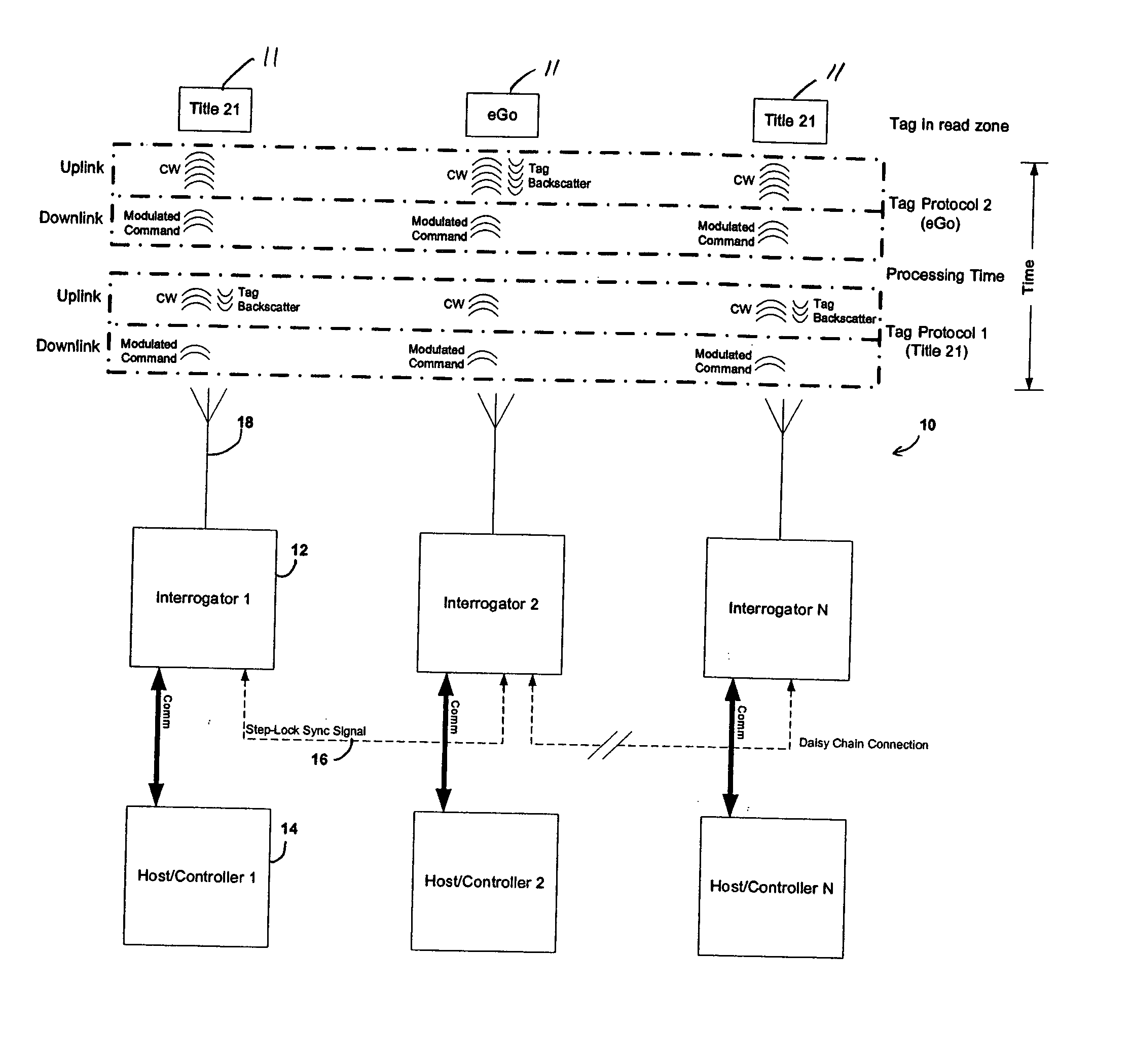
[0038] Turning to the drawings, FIG. 1 is a block diagram of the overall system 10 in accordance with a preferred embodiment of the invention. The system 10 depicts a single cluster of interrogators 12 and hosts or controllers 14 in a step-lock configuration, and various active or backscatter t...


PUM


Abstract

A multi-protocol RFID interrogating system employs a synchronization technique (step-lock) for a backscatter RFID system that allows simultaneous operation of closely spaced interrogators. The multi-protocol RFID interrogating system can communicate with backscatter transponders having different output protocols and with active transponders including: Title 21 compliant RFID backscatter transponders; IT2000 RFID backscatter transponders that provide an extended mode capability beyond Title 21; EGO™ RFID backscatter transponders, SEGO™ RFID backscatter transponders; ATA, ISO, ANSI AAR compliant RFID backscatter transponders; and IAG compliant active technology transponders. The system implements a step-lock operation, whereby adjacent interrogators are synchronized to ensure that all downlinks operate within the same time frame and all uplinks operate within the same time frame, to eliminate downlink on uplink interference.

Description


Claims


Application Information

Patent Timeline
Owner TRANSCORE BERMUDA LICENSE
Why Eureka
Try Eureka