Pointing input system and method using one or more array sensors

a technology of array sensors and input systems, applied in the direction of input/output for user-computer interaction, instruments, computing, etc., can solve the problems of inconvenient use of trackballs for writing on upright screens, touch panels are disadvantageous to alignment and portability for larger screens, and input systems using conventional sensors may often suffer alignment degradation

Inactive Publication Date: 2006-01-12
MICRO NITS
View PDF6 Cites 53 Cited by
  • Summary
  • Abstract
  • Description
  • Claims
  • Application Information

AI Technical Summary

Problems solved by technology

The trackball is not suitable to be used for writing on an upright screen.
The touch panel is disadvantageous to alignment and portability for larger-scale screens.
Due to the significant barrel or pincushion distortion of the optical lens, the input systems using conventional sensors may often suffer the alig...

Method used


Image

  • Pointing input system and method using one or more array sensors
  • Pointing input system and method using one or more array sensors
  • Pointing input system and method using one or more array sensors

Examples


first embodiment

of Pointing Input System

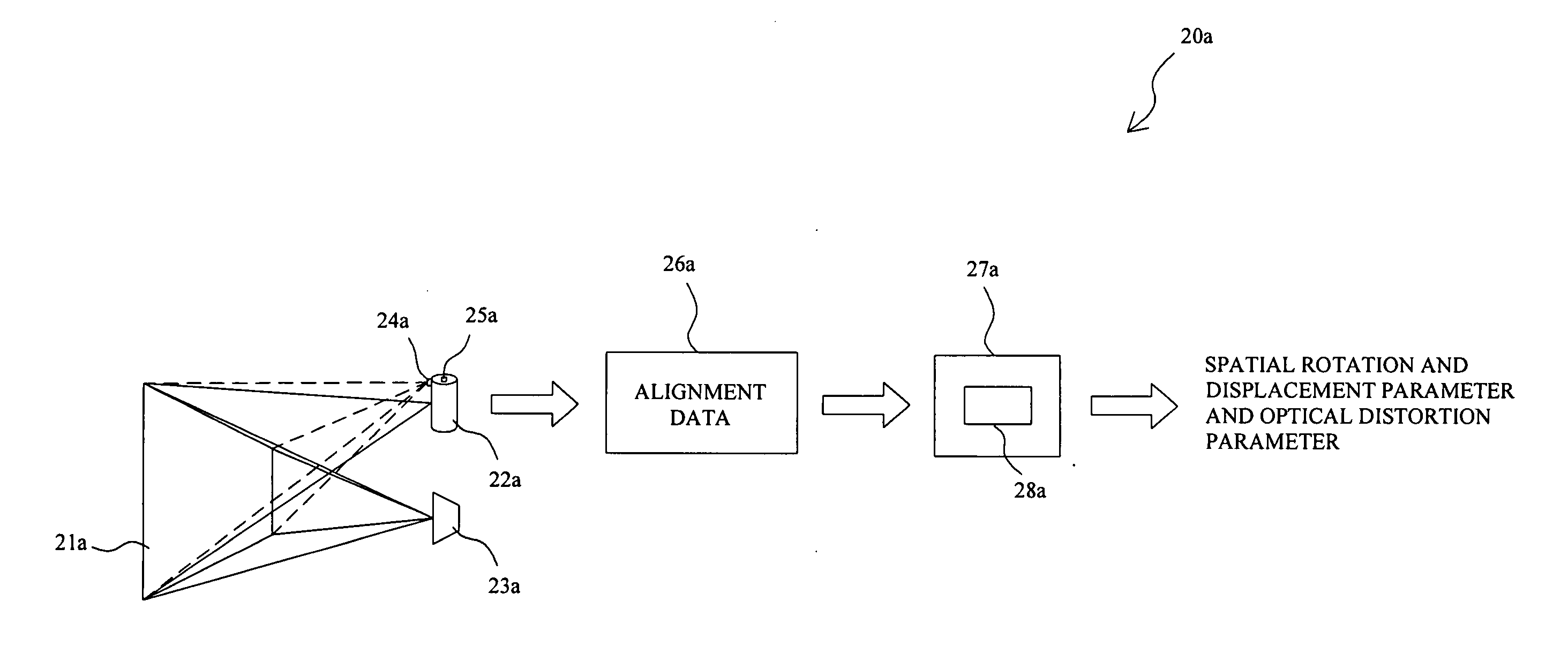
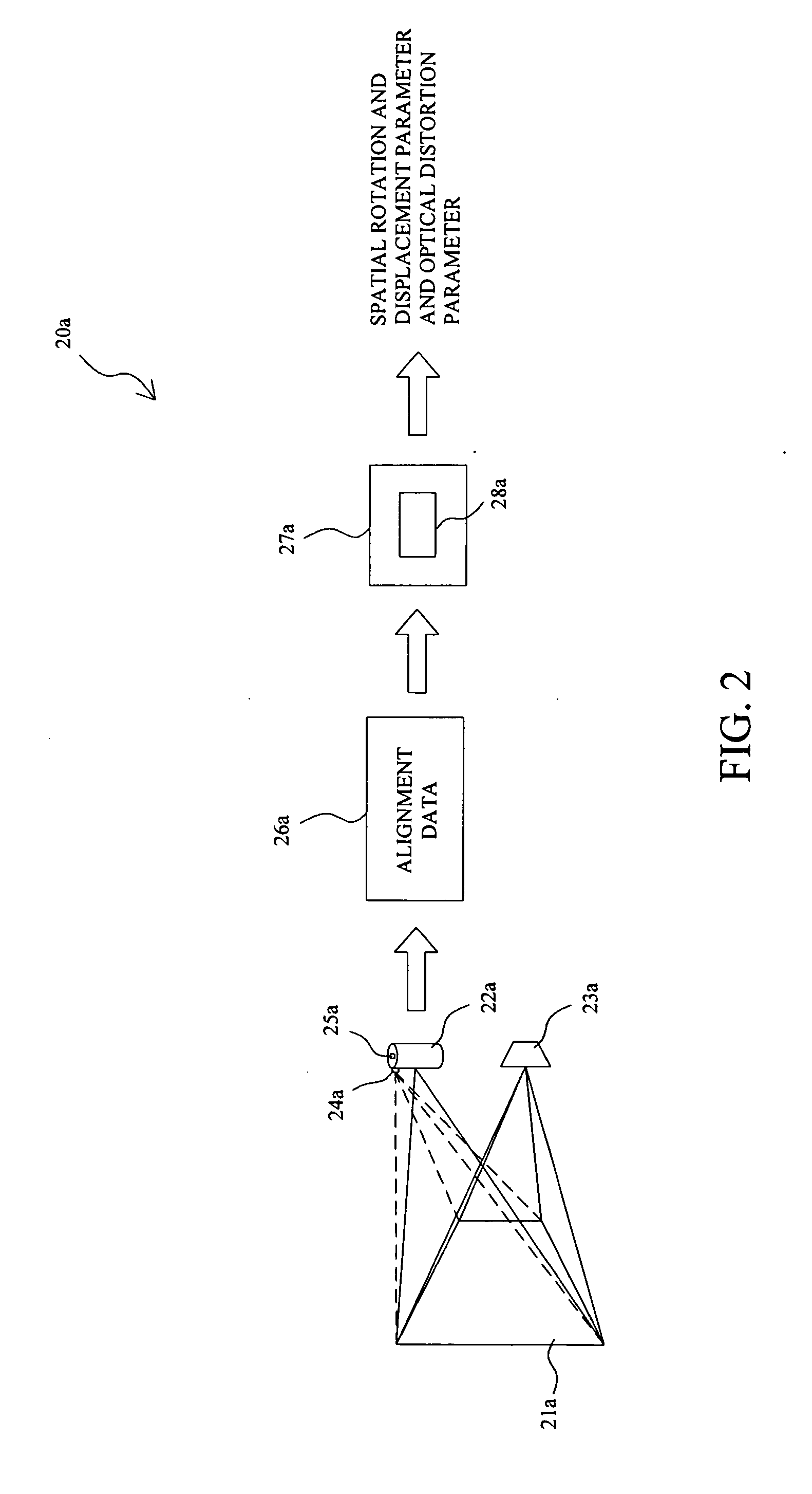
[0025]FIG. 5 shows a pointing input system 40 applied for an information system using single front projector 41 and single array sensor 42. In the pointing input system 40, after an alignment procedure 20a illustrated in FIG. 2, a pointer 46 could be used for direct inputs on a screen 43. The light spot 47 projected by the pointer 42 on the screen 43 is shot by the array sensor 42 to generate a first data including the image information of the light spot 47 sent to a computer system 44, where an identification system 49 running on the computer system 44 retrieves a second data including the position information of the light spot 47 from the first data based on the optical distortion parameter and spatial rotation and displacement parameter that are obtained by the alignment procedure 20a. The second data is provided for the projector 41 to display a correlated output on the screen 43. In FIG. 5, the correlated output is an image of the light spot 47, while in...

second embodiment

of Pointing Input System

[0026]FIG. 6 shows a pointing input system 50 applied for an information system using single front projector 51 and multiple array sensors 52. After an alignment procedure 20a illustrated in FIG. 2, the system 50 allows a pointer 46 to directly input on a screen 53. The array sensors 52 are arranged in different directions to shoot on the screen 53, and thus, if one of them is unable to shoot the light spot on the screen 53 properly, another is switched instead to shoot on the screen 53, so as to achieve the purpose of full viewing angle without any loss. Since several array sensors 52 are provided in the system 50, the screen 53 may have very large area for display. The other operations are referred to the first embodiment 40 illustrated in FIG. 5. The identification system is not shown in FIG. 6 for simplicity.

third embodiment

of Pointing Input System

[0027]FIG. 7 shows a pointing input system 60 applied for an information system using multiple front projectors 61, multiple array sensors 62, and multiple pointers 63. In this system 60, a screen 64 is defined to have several projection regions each one is responsible by a projector 61 to display thereon and by an array sensor 62 to shoot thereon, so as to improve the resolution. After an alignment procedure 20a illustrated in FIG. 2, the pointers 63 are allowed in this system60 for direct inputs on the screen 64. By using the pointers 63, it is achieved multiple inputs from several persons or opinion exchanges between several persons, without any additional equipments. Using the pointers 63 for direct inputs on the screen 63 may be referred to the first embodiment 40 illustrated in FIG. 5. The identification system is not shown in FIG. 7 for simplicity.


PUM


Abstract

In a pointing input system and method, a pointer applies a light spot on a screen, an array sensor shoots on the screen to generate a first data for an identification system to retrieve a second data therefrom, the second data includes the position information of the light spot for an information system to apply a correlated output on the screen. The second data is generated based on an optical distortion parameter and a spatial rotation and displacement parameter determined by an alignment procedure that comprises applying an input for alignment on the screen for the array sensor to shoot to generate an alignment data, and comparing the alignment data with a reference data.

Description

FIELD OF THE INVENTION [0001] The present invention is related generally to a system and method for direct inputs on a screen and more particularly, to a pointing input system and method for an information system. BACKGROUND OF THE INVENTION [0002] Current input apparatus available for information systems includes keyboard, mouse, trackball, light pen, and touch panel. The trackball is not suitable to be used for writing on an upright screen. The light pen is only available for the inputs on a scanning screen such as Cathode-Ray Tube (CRT) screen, but not for the inputs on a high resolution screen. The touch panel is disadvantageous to alignment and portability for larger-scale screens. Due to the significant barrel or pincushion distortion of the optical lens, the input systems using conventional sensors may often suffer the alignment degradation caused by the mistakes or unintentional touches to the equipment, and even have to be suspended during its use accordingly. Therefore, si...

Claims


Application Information

Patent Timeline
IPC IPC(8): G09G5/00G06F3/042G06F3/03G06F3/041
CPCG06F3/0386G06F3/0425G06F3/0418G06F3/04182
Inventor TING, ALBERT
Owner MICRO NITS
Why Eureka
Try Eureka