Haptic feedback input device

a technology of input device and feedback, which is applied in the direction of mechanical control device, manual control with single controlling member, instruments, etc., can solve the problems of large force required to pivotably operate the manual operating section, and the sensitivity of the click feeling imparted by the click feeling imparting unit deteriorates, so as to improve the sensitivity of the click feeling

Inactive Publication Date: 2006-01-12
ALPS ALPINE CO LTD
View PDF5 Cites 7 Cited by
  • Summary
  • Abstract
  • Description
  • Claims
  • Application Information

AI Technical Summary

Benefits of technology

[0008] The invention has been made in order to solve the above-described problems in the related art, and it is an object of the invention to provide a haptic feedback inpu...

Problems solved by technology

Therefore, there is a disadvantage in that large force is required to pivotably operate the manual operatin...

Method used


Image

  • Haptic feedback input device
  • Haptic feedback input device
  • Haptic feedback input device

Examples


Embodiment Construction

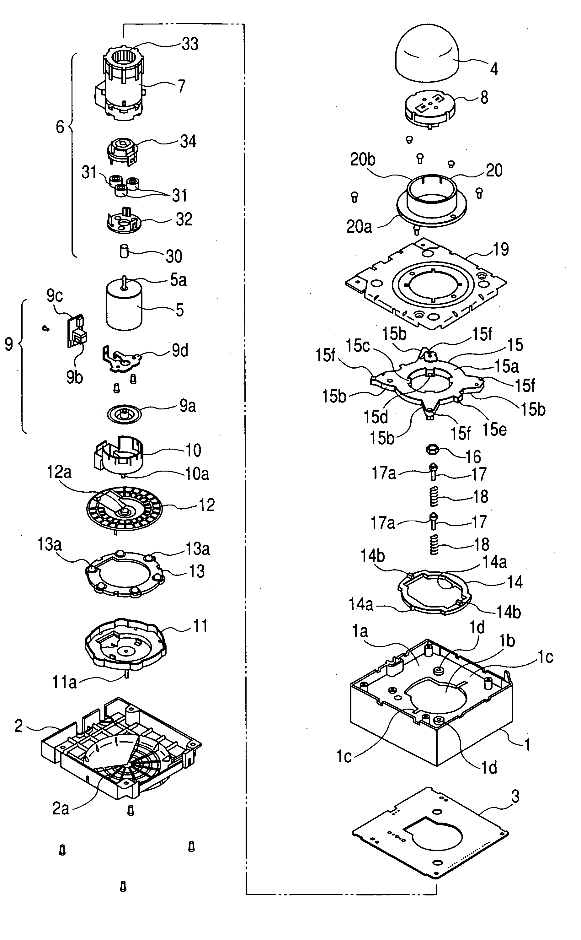
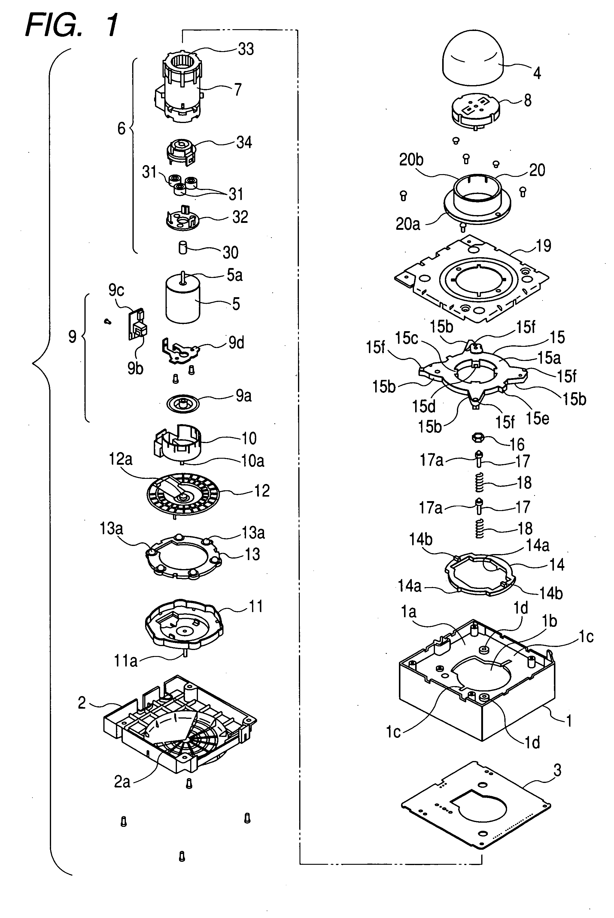
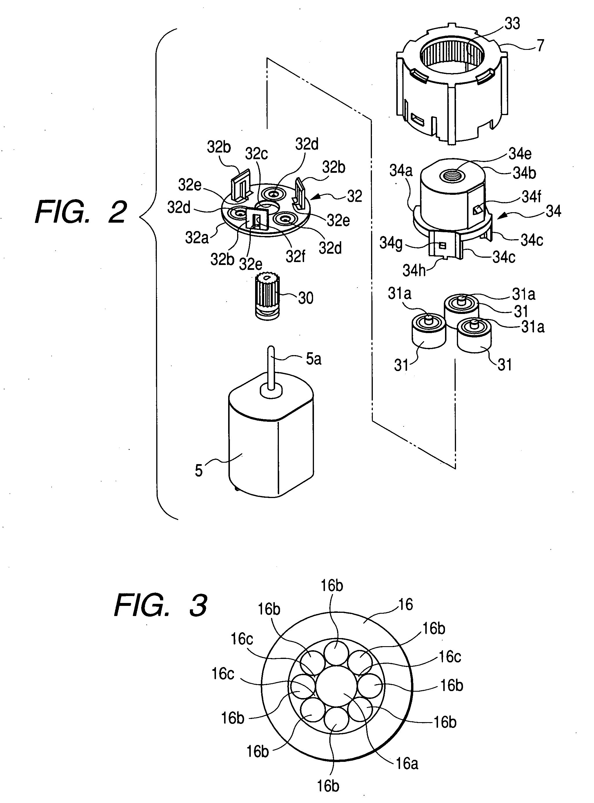
[0024] Hereinafter, an embodiment of a haptic feedback input device according to an embodiment of the invention will be described with reference to FIGS. 1 to 6. FIG. 1 is an exploded perspective view of a haptic feedback input device according to the embodiment. FIG. 2 is an exploded perspective view of a planetary gear mechanism included in the haptic feedback input device according to the embodiment in an enlarged scale. FIG. 3 is a plan view of a cam member included in the haptic feedback input device according to the embodiment. FIG. 4 is a cross-sectional view of the assembled haptic feedback input device according to the embodiment. FIG. 5 is a cross-sectional view of the haptic feedback input device according to the embodiment at the time of a pivot operation. FIG. 6 is a graph showing the comparison result of the advantages of the invention to those of the related art.

[0025] As shown in FIG. 1, the haptic feedback input device according to the embodiment includes a case 1,...


PUM


Abstract

A haptic feedback input device includes an operating section that is operated by a user, a motor that pivots in conjunction with the pivot operation of the operating section, a base that pivotably holds the motor via a pivot holder (motor supporting section), a cam member and driving rods (click feeling imparting unit) which impart a click feeling according to the pivot operation of the operating section. The pivot center of the motor is disposed below the center of gravity of the motor.

Description

BACKGROUND OF THE INVENTION [0001] 1. Field of the Invention [0002] The present invention relates to a haptic feedback input device, and more particularly, to a haptic feedback input device, having a motor being directly and pivotably operated by an operating section to impart a feedback force, that can improve pivot operability of the motor. [0003] 2. Description of the Related Art [0004] As an input device capable of collectively controlling various in-vehicle electrical apparatuses, such as an air conditioner, a radio, a television, a CD player, a navigation system, and the like, the inventors has been proposed a manual input device. Referring to FIG. 7, the manual input device includes a motor 102 that is pivotably attached to a frame 101, a manual operating section 103 that is attached to a motor driving shaft 102a, a first position sensor 104 that detects a pivot direction and a pivot distance of the motor 102, a second position sensor 105 that detects a rotation direction and...

Claims


Application Information

Patent Timeline
IPC IPC(8): G09G5/08G05G5/03G05G9/047
CPCG05G5/03G05G5/05H01H2003/008G05G2009/04759G05G9/04792
Inventor ONODERA, KAZUNOBUMAEDA, TAKUYA
Owner ALPS ALPINE CO LTD
Why Eureka
Try Eureka