Inkjet printer

a printer and inkjet technology, applied in the direction of printing, other printing apparatus, etc., can solve the problems of pressure loss in the structure of the inkjet printer becomes complicated, and the diameter or length of the ink supply pipe is difficult to realize, so as to achieve high quality, high viscosity, and high viscosity

Active Publication Date: 2006-01-12
KONICA MINOLTA MEDICAL & GRAPHICS INC
View PDF8 Cites 64 Cited by
  • Summary
  • Abstract
  • Description
  • Claims
  • Application Information

AI Technical Summary

Benefits of technology

[0031] According to the present invention, because high viscosity ink with a viscosity of 10-500 mpa·s at 30° C. is used, high quality image recording can be performed without causing ink flow or the like on the recording medium P even for recording medium P which does not absorb ink. In addition, in the case where this type of high viscosity ink is also used, the effect is seen in which ink pressure loss is reduced and ink jetting can be performed smoothly, and the state where there is no ink remaining in the ink tank can be easily detected.
[0032] Because the ink is heated to 30-150° C. and then jetted from the recording head, image recording is performed while the jetting of ink from the nozzle is maintained in a favorable state and furthermore, because jetting can make small droplets such that one dot of the droplets is 2-20 pl, high quality images can be obtained even with high viscosity inks. In addition, in this case also, the effect is seen in which ink pressure loss is reduced and ink jetting can be performed smoothly, and the state where there is no remaining ink in the ink tank can be easily detected.
[0033] According to the present invention, because the ink is cured by irradiating ultraviolet light on the ink, image formation is possible on recording medium exhibiting very little ink absorption such as resin films and the like and also in this case, the effect is seen in which ink pressure loss is reduced and ink jetting can be performed smoothly, and the state where there is no ink remaining in the ink tank can be easily detected.
[0034] According to the present invention, because the ink is cured by irradiating ultraviolet light on the ink, image formation is possible on recording medium exhibiting very little ink absorption such as resin membranes and the like and in this case also, the effect is seen in which ink pressure loss is reduced and ink jetting can be performed smoothly, and the state where there is no ink remaining in the ink tank can be easily detected.
[0035] Furthermore, according to the present invention, even when a high viscosity ink is used, and in particular in the case where a cationic polymerization ultraviolet-light curable ink having a monomer as the main component is used, the effect is seen in which ink pressure loss is reduced and ink jetting can be performed smoothly, and the state where there is no ink remaining in the ink tank can be easily detected.
[0036] According to the present invention, in the case where image recording is performed on a recording medium which does not absorb ink such as a resin or the like, because spreading of the ink on the recording medium is prevented, a high viscosity ink can be used, and in this case also, the effect is seen in which ink pressure loss is reduced and ink jetting can be performed smoothly, and the state where there is no ink remaining in the ink tank can be easily detected.

Problems solved by technology

In such an inkjet printer, when high viscosity ink is employed for image recording, pressure loss is caused in the ink supplying pipe because of frictional resistance.
As a result, in the case of sequential jetting of ink from the recording head nozzle, ink cannot be led to the nozzle only by the jetting force and a jetting defect may be caused.
However, there is a problem that it is difficult to realize this situation regarding the diameter or length of the ink supply pipe by reason of the designing difficulty of inkjet printer.
In the case of installation of a sub-tank by the recording head or a back pressure controlling pump, the structure of the inkjet printer becomes complicated.
Especially, to position sub-tanks near the recording head, sub-tanks the number of which is corresponding to that of recording head needed to be mounted on the carriage and it causes upsizing and weight increase of carriage and further causes upsizing and weight increase of the apparatus itself.
Furthermore, reinforcement of the driving system to drive such a large carriage is needed and there is a problem that it increases the apparatus cost.
As a result, in the method providing a weight sensor in the ink tank, when an attempt is made to detect the weight of the ink inside the ink tank, the weight of these parts is also measured along with the weight of the ink in the tank, and this caused a problem in that weight measurement could not be performed with high accuracy.
Further, there were also sometimes jetting abnormalities due to missing nozzles and the like, or ink would be forcibly absorbed from the nozzle at the time of cleaning the recording head, or sometimes there would be ink outflow as a result of air jetting.
However, the method of counting the quantity of ink ejected during image recording does not count this type of ink outflow, and in addition, because high accuracy management of the ink outflow due to jetting abnormalities and ink outflow at the time of cleaning is difficult, there was a problem in that the quantity of ink remaining could not be accurately determined.

Method used


Image

  • Inkjet printer
  • Inkjet printer
  • Inkjet printer

Examples


Embodiment Construction

[0042] The following is a description of the first embodiment of the inkjet printer of this invention with reference to the accompanying drawings.

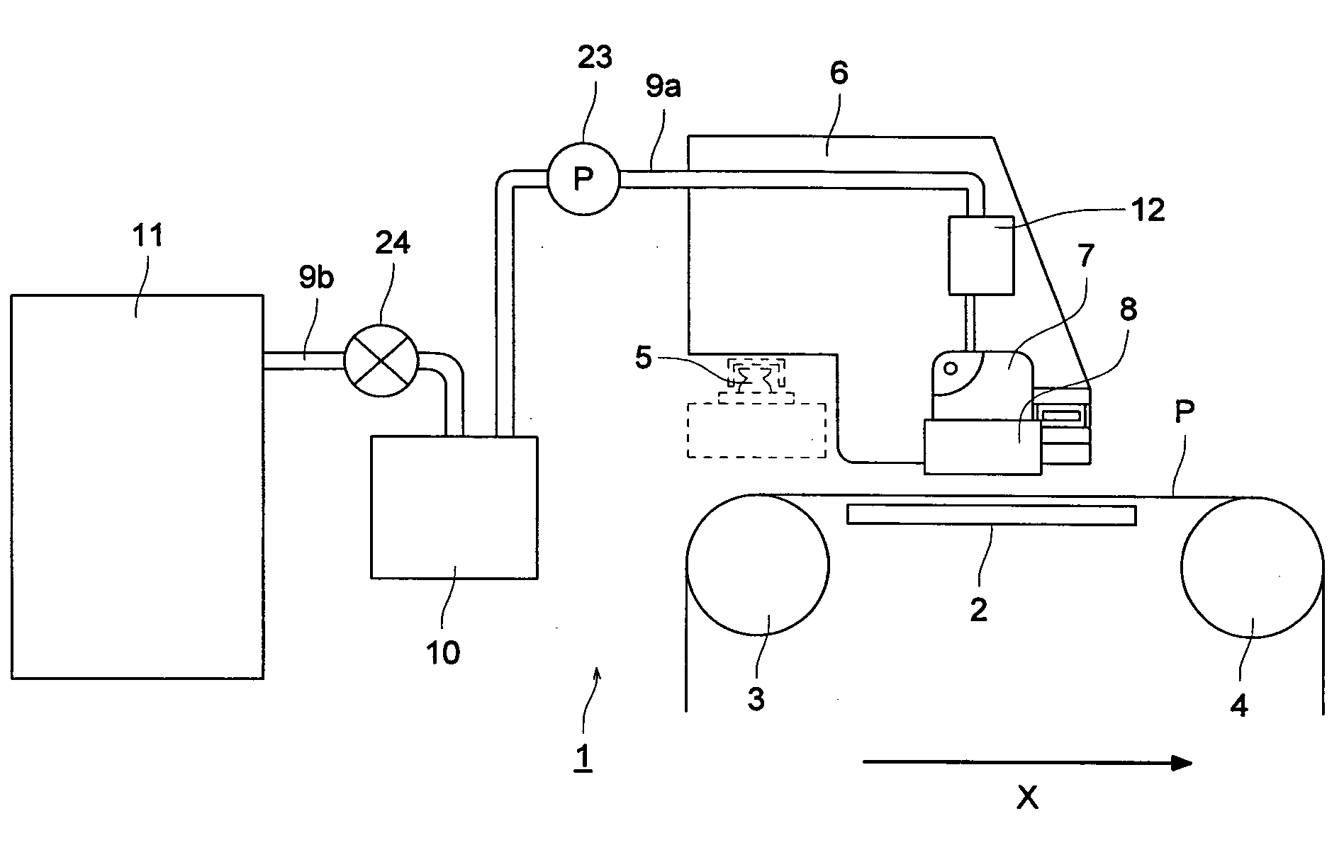
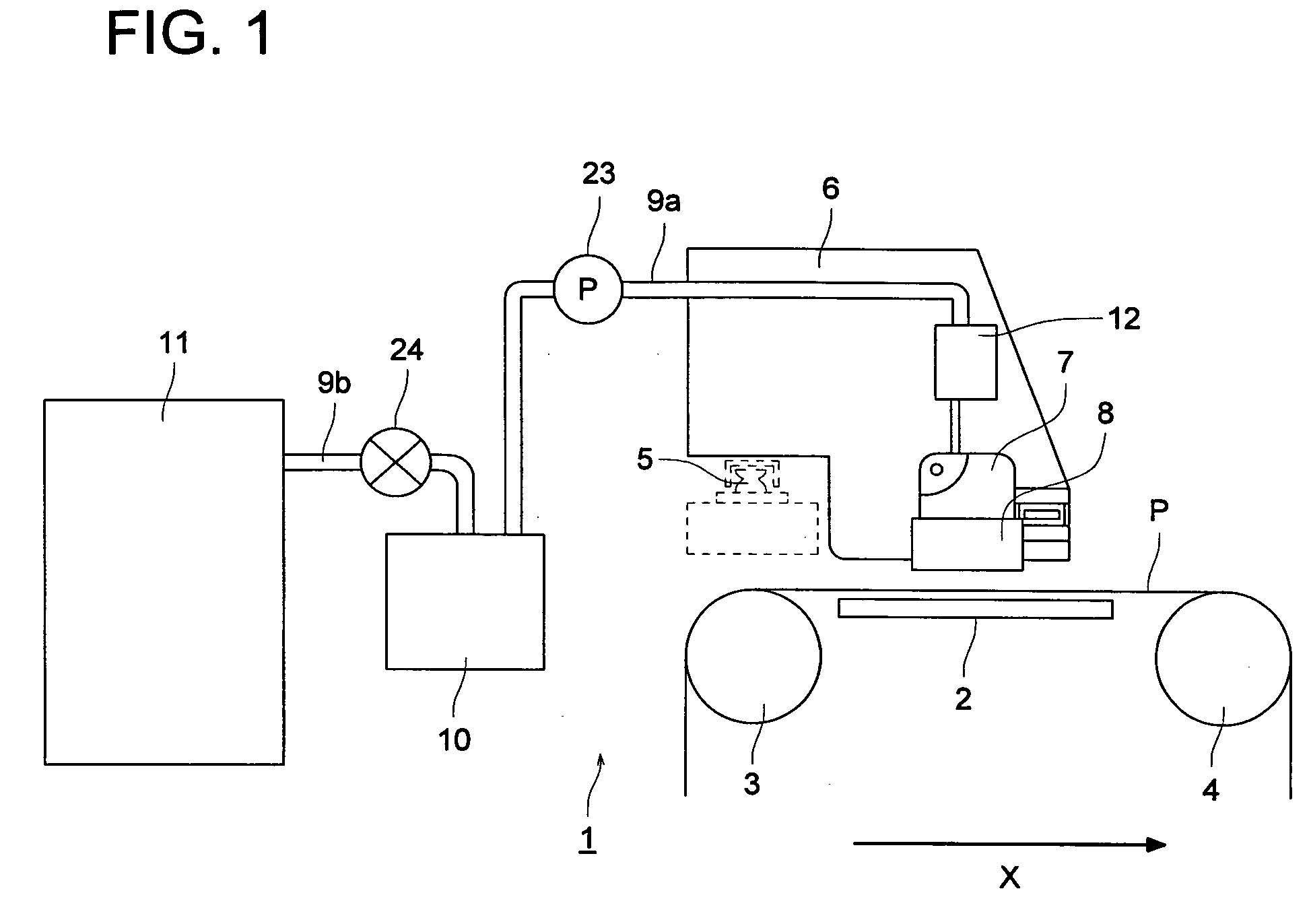
[0043] First, as shown in FIG. 1, in the present embodiment, inkjet printer 1 is a serial print type inkjet printer, and this inkjet printer 1 has flat platen 2 which supports flat recording medium P on its non-recording side. Conveying rollers 3 and 4 which convey the recording medium P while keeping it at substantially the same height as the platen 2 are provided so as to be rotatable at the upstream side and the downstream side respectively of platen 2. Recording medium P is conveyed in prescribed conveyance direction X along the upper surface of platen 2 by recording medium conveying mechanism 30 (See FIG. 3) due to rotation of conveying rollers 3 and 4.

[0044] Rod-shaped guide rail 5 which extends in the main scanning direction which is perpendicular to conveyance direction X of recording medium P is provided above platen 2. Carriage...


PUM


Abstract

Installed are intermediate tank 12 with damping function against pressure fluctuation for temporarily storing ink in a position within ink supplying pipe 9a which supplies ink from main tank 11 to recording head 7, liquid supplying pump 23 between main tank 11 and intermediate tank 12 for supplying ink to intermediate tank 12 and controller 25 actuating liquid supplying pump 23 to supply ink from main tank 11 to intermediate tank 12 when membrane surface detecting sensor 19 detects that the quantity of remaining ink in intermediate tank 12 is less than a prescribed one. When liquid supplying pump is actuated and no increase of quantity of remaining ink in intermediate tank 12 is detected, controller 25 judges that that there is no remaining ink in main tank 11 and a result of the judgment is notified by display section 28.

Description

[0001] This application is based on Japanese Patent Application Nos. 2004-200338 and 2004-200363 filed on Jul. 7, 2004 in Japanese Patent Office, the entire content of which is hereby incorporated by reference. BACKGROUND OF THE INVENTION [0002] The present invention relates to an inkjet printer and in particular to an inkjet printer for performing image recording using high viscosity ink. [0003] Inkjet printers are generally known as a means to perform printing on various recording media. Inkjet printer refers to a printer in which image recording on a recording medium is performed when ink in the form of small droplets is emitted from the nozzle of the recording head, using a piezoelectric element or a heater for example onto a recording medium such as paper or the like, and the recording head is moved over the recording medium while the ink penetrates or is fixed on the recording medium. Inkjet printers have the advantage that printing on demand is possible since a plate-making p...

Claims


Application Information

Patent Timeline
Patent Type & Authority Applications(United States)
IPC IPC(8): B41J2/195
CPCB41J2/175
Inventor TANNO, RYUJIMATSUSHIMA, KOJI
Owner KONICA MINOLTA MEDICAL & GRAPHICS INC
Why Eureka
Try Eureka