Check patentability & draft patents in minutes with Patsnap Eureka AI!

Frame processing and frame processing method

a frame processing and frame technology, applied in the field of frame processing system and frame processing method, can solve the problems of insufficient light, failure to obtain desirable picture quality in some cases, and difficulty in obtaining desirable picture quality over the output picture fram

Inactive Publication Date: 2006-01-12
NISSAN MOTOR CO LTD
View PDF4 Cites 4 Cited by
  • Summary
  • Abstract
  • Description
  • Claims
  • Application Information

AI Technical Summary

Benefits of technology

[0010] It is therefore an object of the present invention to provide a frame processing system and a frame processing method capable of avoiding such a situation where the local brightness of an input frame affects an output picture frame in its entirety so that the output picture frame is entirely made excessively bright or dark to fail to obtain a desirable picture quality, thereby enabling obtainment of an output picture frame which is easy to view accordingly.

Problems solved by technology

As such, the local brightness of the input frame affects the output picture frame in its entirety so that the output picture frame is entirely made excessively bright or dark, thereby failing to obtain a desirable picture quality in some cases.
Further, adopting a super-wide-angle lens in an electronic camera results in an insufficient amount of light at an edge of the lens so that the picked-up picture is made darker at a peripheral portion than at a central portion.
When the frame of such a picture is processed based on the brightness at its central portion, the reconstructed picture frame is also made dark at its peripheral portion, thereby making it difficult to obtain a desirable picture quality over an output picture frame.

Method used


Image

  • Frame processing and frame processing method
  • Frame processing and frame processing method
  • Frame processing and frame processing method

Examples


first embodiment

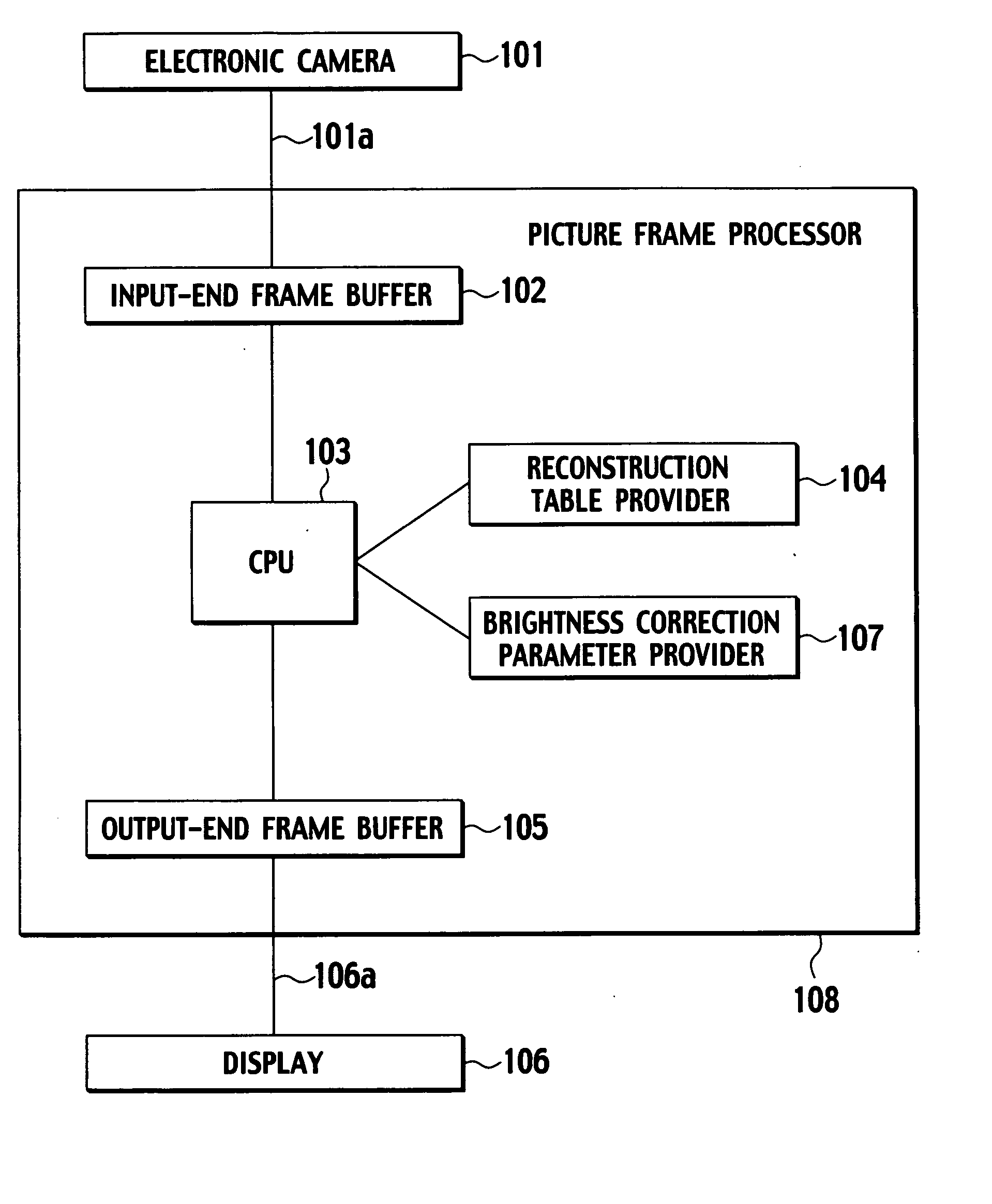
[0028] There will be explained a frame processing system according to a first embodiment of the present invention with reference to FIGS. 1 through 6.

[0029] As shown in FIG. 1, the frame processing system includes: an input interface 101a configured to input a set of data on whole pixels of a picked-up picture by a vehicle-mounted electronic camera 101, as a picture frame; a frame processor 108 configured to process at least part of the picture frame input via the interface 101a, for a reconstruction thereof into a picture frame of an adaptive format to a vehicle-mounted display 106, with a pixelwise brightness correction inclusive; and an output interface 106a configured to output at least part of the picture frame thus reconstructed, to the display 106. The interfaces 101a, 106a may each be a suitable signal transfer line, circuit, or communication system.

[0030] The picture frame processor 108 includes: an input-end frame buffer 102 connected to the input interface 101a; a CPU 1...

second embodiment

[0063]FIG. 7 shows a frame processing system according to a second embodiment of the present invention.

[0064] The frame processing system includes the brightness correction parameter provider constituted as a brightness correction parameter calculator 207 configured to calculate pixel coordinates x—in and y—in from an argument address adr—in passed from the CPU 103. Here, x—in and Y—in of each address adr—in can be represented by a residue part and an integer part of an equation “adr—in modulo Xmax—in”, respectively. For example, when the argument address adr—in is 101 and the Xmax—in is 10, x—in has a value of 1 and y—in has a value of 10.

[0065] The brightness correction parameter calculator 207 has a reference point represented by coordinates (x—base, y—base). These coordinates may be (Xmax—in / 2, Ymax—in / 2) for a central point of the input-end frame buffer 102. The brightness correction parameter calculator 207 is configured to obtain a direct distance L connecting between each ...

third embodiment

[0081]FIG. 11 shows a frame processing system according to a third embodiment of the present invention.

[0082] The frame processing system includes the brightness correction parameter provider constituted as a brightness correction parameter calculator 307 configured to calculate pixel coordinates x—in and y—in from an argument address adr—in passed from the CPU 103.

[0083] The brightness correction parameter calculator 307 is configured to obtain a pixel location defined by: a direct distance L between each pixel and a reference point; and an angle θ formed between (i) a line connecting between the pixel and the reference point, and (ii) a line parallel to a horizontal coordinate axis; and to use a function f(L, θ) including the direct distance L and angle θ as arguments to thereby obtain a calculation result as a brightness correction parameter “a” which is returned to the CPU 103.

[0084] The manner, where a brightness of a pixel data color—in is pixelwise corrected in the CPU 103...


PUM


Abstract

A picture frame input from an electronic camera is stored in an input-end buffer frame, and read therefrom in a CPU, where it is processed, using a reconstruction table defining a pixelwise image reconstruction and using a correction parameter defining a pixelwise brightness correction, having resultant data stored in an output-end frame buffer, where a corresponding picture frame is reconstructed to be output to a display.

Description

BACKGROUND OF THE INVENTION [0001] 1. Field of the Invention [0002] The present invention relates to a frame processing system and a frame processing method configured to process a frame of picture (hereinafter called “picture frame” or “frame”), and more particularly to a frame processing system and a frame processing method configured to process a picture frame and adaptive for use in a vehicle. [0003] 2. Description of Relevant Art [0004] Japanese Patent Application Laid-Open Publication No. 10-248024 has disclosed a picture frame processing system for a vehicle. [0005] The picture frame processing system is configured to store a picture frame input from a vehicle-mounted electronic camera in an input-end frame buffer, to reconstruct the stored frame by means of a frame reconstruction table, and to store the reconstructed frame as a frame to be output in an output-end frame buffer. SUMMARY OF THE INVENTION [0006] The frame processing system is configured to uniformly reconstruct ...

Claims


Application Information

Patent Timeline
Patent Type & Authority Applications(United States)
IPC IPC(8): H04N5/222
CPCH04N5/3572H04N25/61G06T1/20G06T7/00
Inventor OIZUMI, KEN
Owner NISSAN MOTOR CO LTD
Features
  • R&D
  • Intellectual Property
  • Life Sciences
  • Materials
  • Tech Scout
  • Unparalleled Data Quality
  • Higher Quality Content
  • 60% Fewer Hallucinations
Learn More