Fixing unit and image-forming device using the same

a technology of fixing unit and image forming device, which is applied in the direction of instruments, electrographic process devices, optics, etc., can solve the problems of increasing the cost of the image forming device, halting the supply of power, and losing the fixing function

Active Publication Date: 2006-01-12
BROTHER KOGYO KK
View PDF18 Cites 18 Cited by
  • Summary
  • Abstract
  • Description
  • Claims
  • Application Information

AI Technical Summary

Benefits of technology

[0012] In view of the foregoing, it is an object of the present invention to provi

Problems solved by technology

Since failure if the halogen lamp is fatal to the image-forming device, resulting in a loss of the fixing function, the fixing unit must be configured in such a way as to be easily replaceable.
Upon reaching a prescribed fusing temperature, the resin melts, causing a spring provided in the fuse to break the

Method used


Image

  • Fixing unit and image-forming device using the same
  • Fixing unit and image-forming device using the same
  • Fixing unit and image-forming device using the same

Examples


Embodiment Construction

[0031] An image-forming device according to a preferred embodiment of the present invention will be described while referring to the accompanying drawings.

(1) Overall Structure of a Laser Printer

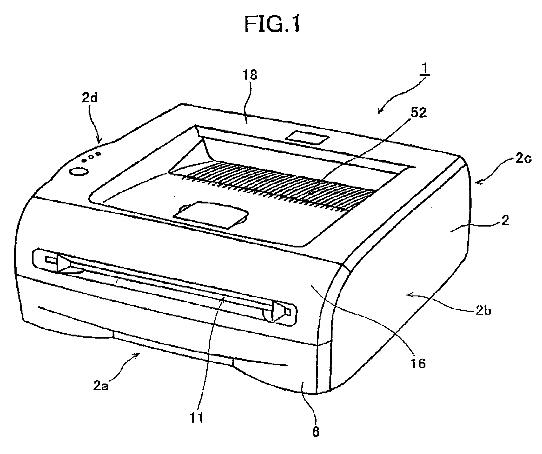
[0032] Referring to FIG. 1, a laser printer 1 includes a casing 2 having a top cover 16 forming the top surface of the casing 2, and four side surfaces 2a, 2b, 2c, and 2d (side surfaces 2c and 2d are not visible in FIG. 1) A portion of the top cover 18 is recessed inward to form a sheet discharge tray 52. A paper cassette 6 is provided in the bottom section of the casing 2 and can be inserted into or removed from the casing 2 through the front side surface 2a. The paper cassette 6 can accommodate a plurality of sheets of paper or other recording medium. The front side surface 2a also includes a front cover 16 that can swing open or closed on the front of the casing 2, and a manual feed tray 11 provided on the front cover 16 for hand feeding a recording medium one sheet at a time.

[0033] N...


PUM


Abstract

A fixing unit of an image-forming device having a heating roller, a pressure roller disposed in confrontation with the heating roller, and a case that rotatably supports the heating roller on both longitudinal ends thereof and covers the heating roller from the side opposite the pressure roller, while leaving the pressure roller exposed. A pair of pressure roller support plates, one end of which is supported on the case, rotatably supports both ends of the pressure roller. With this construction, a more compact fixing unit can be achieved than when the case is configured to cover the heating roller and pressure roller entirely. The fixing unit includes a temperature fuse for restraining abnormal temperature rises in the heating roller, and a temperature fuse cover that extends from an inner wall of the case to provide insulation between the temperature fuse and the heating roller. By integrally forming the temperature fuse cover with the case, it is possible to reduce the manufacturing costs of the fixing unit. Support members may also be provided between a bottom surface of the case and the temperature fuse cover to restrain deformation of the temperature fuse cover.

Description

BACKGROUND CF THE INVENTION [0001] 1. Technical Field [0002] The present invention relates to a fixing unit and an image-forming device for fixing toner images that have been transferred onto a paper or other recording medium. [0003] 2. Description of the Related Art [0004] Conventionally, electrophotographic image-forming devices, such as laser printers, are equipped with a light-emitting unit including a laser diode for emitting a light beam, and a photosensitive member, the surface of which carries a uniform charge. When the surface of the photosensitive member is exposed to the light beam, electrostatic latent images are formed on the surface of the photosensitive member and the latent images are then developed into visible images with toner. Subsequently, the visible images are transferred onto a paper or other recording medium to form visible toner images thereon. [0005] However, the images transferred onto the recording medium are merely carried to the recording medium by an ...

Claims


Application Information

Patent Timeline
IPC IPC(8): G03G15/20
CPCG03G2221/1639G03G21/1685G03G15/2064
Inventor ARATACHI, TOMITAKEITO, TERUMASA
Owner BROTHER KOGYO KK
Why Eureka
Try Eureka