Outboard motor control system

a control system and motor technology, applied in waterborne vessels, marine propulsion, vessel construction, etc., can solve the problem of slow boat speed not being low enough

Inactive Publication Date: 2006-01-12
HONDA MOTOR CO LTD
View PDF3 Cites 31 Cited by
  • Summary
  • Abstract
  • Description
  • Claims
  • Application Information

AI Technical Summary

Benefits of technology

[0007] An object of this invention is therefore to overcome this inconvenience by providing an outboard motor control syst

Problems solved by technology

In addition, since the propeller is usually shaped for optimum performance at maximum engine speed, the dead slow boat speed may not be low enough when the outboard motor is kept in-gear.
During very low-speed cruising using a conventiona

Method used


Image

  • Outboard motor control system
  • Outboard motor control system
  • Outboard motor control system

Examples


first embodiment

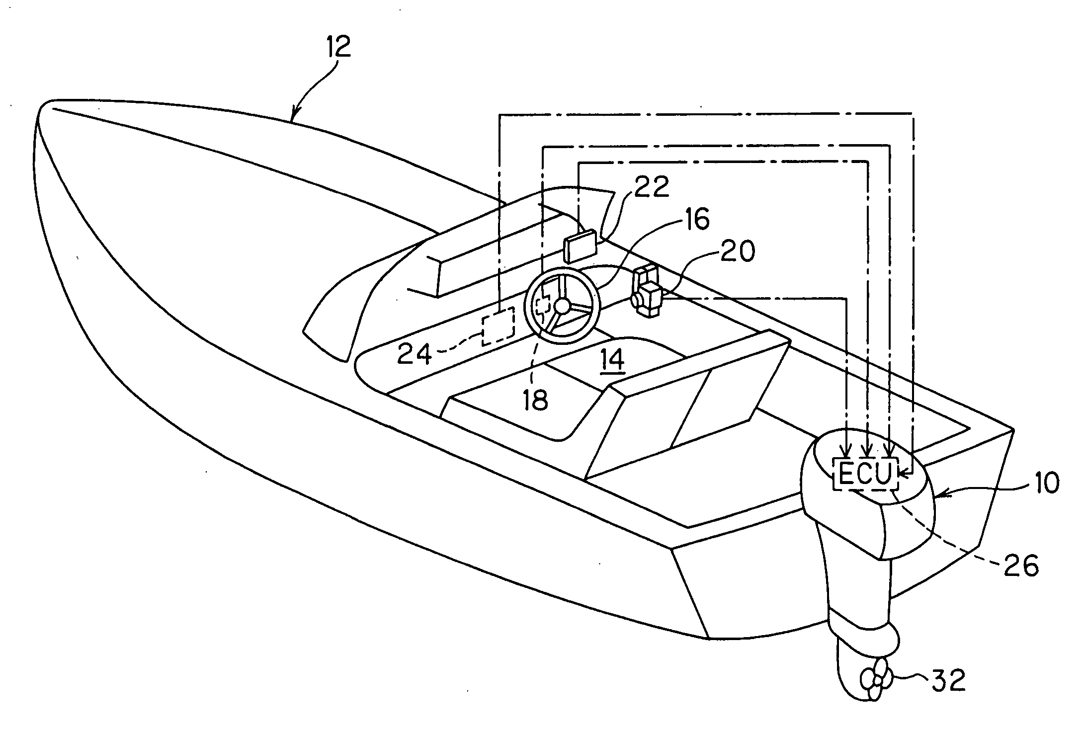
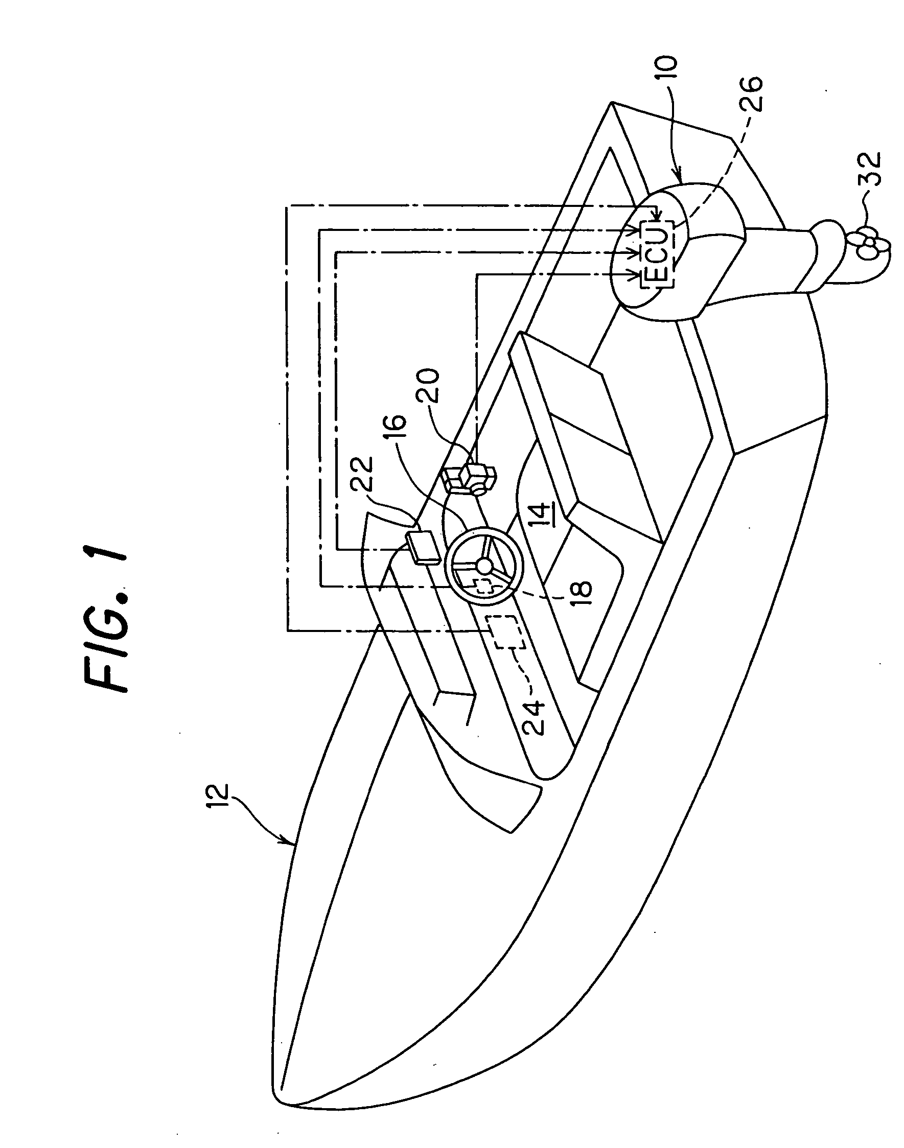
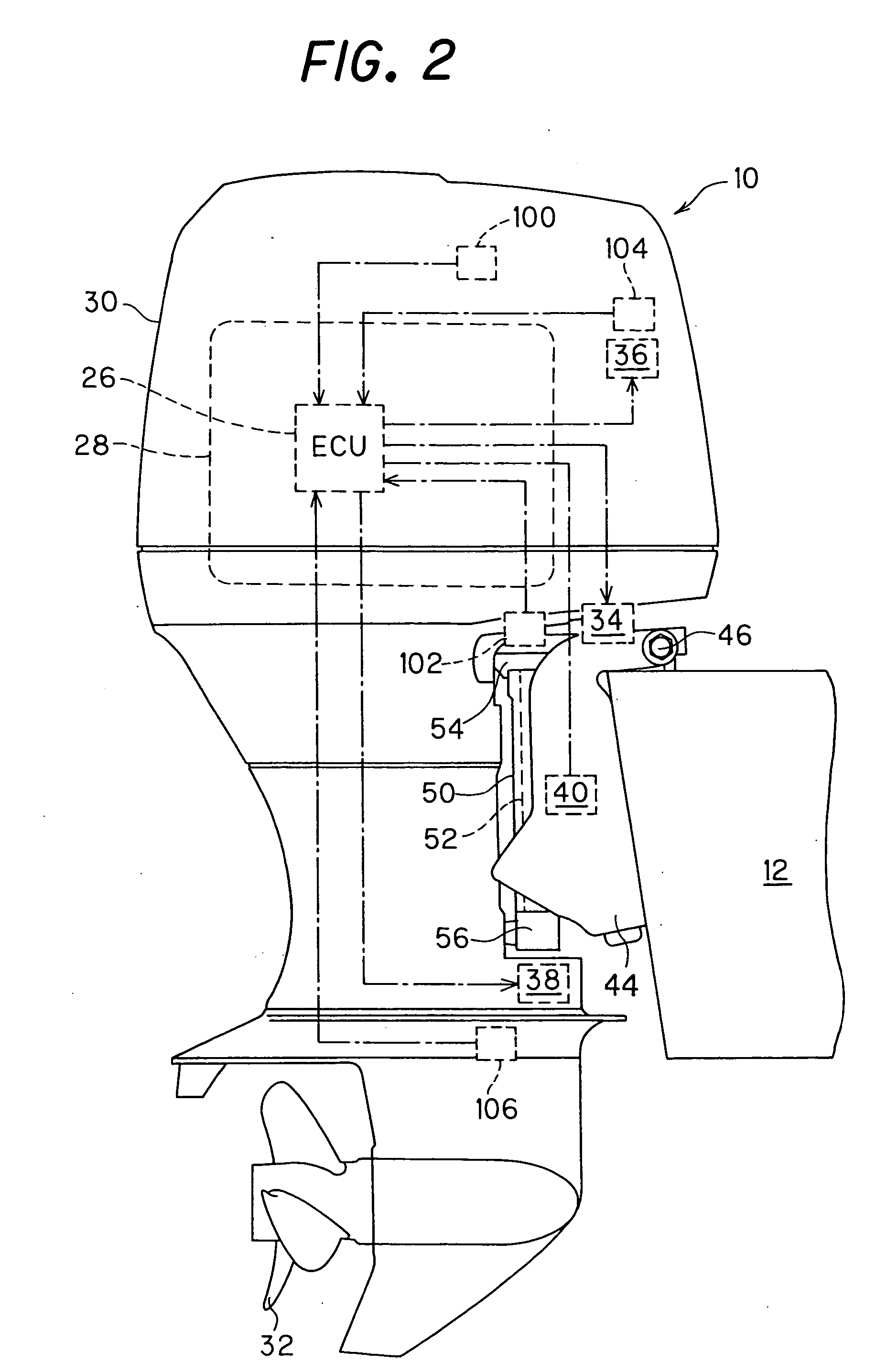
[0018]FIG. 1 is an overall schematic view of an outboard motor control system including a hull (boat) according to the invention and FIG. 2 is a side view of the outboard motor shown in FIG. 1.

[0019] In FIGS. 1 and 2, the symbol 10 indicates an outboard motor. The outboard motor 10 is mounted on the stem (transom) of a hull (boat) 12.

[0020] As shown in FIG. 1, a steering wheel 16 is installed near the operator's seat 14 of the boat 12. A steering wheel angle sensor 18 is installed near a shaft (not shown) of the steering wheel 16 and outputs or generates a signal indicative of the rotation amount (angle) of the steering wheel 16 manipulated by the operator. A remote control box 20 is installed near the operator's seat 14. The remote control box 20 comprises levers and a switch (explained later) that outputs or generates signals in response to the manipulation of the operator.

[0021] A GPS (Global Positioning System) 22 and a control panel 24 are further installed near the operator'...

second embodiment

[0058] An outboard motor control system in accordance with the invention will now be explained.

[0059]FIG. 6 is a block diagram, similar to FIG. 4, but showing the configuration of the outboard motor control system according to the second embodiment.

[0060] As shown in FIG. 6, in the second embodiment, the low-speed cruising switch 120, shift change period setting switch 122 and throttle opening setting switch 124 provided in the control panel 24 in the first embodiment are replaced with a constant-speed cruising switch (instruction switch) 130 for enabling the operator to input an instruction to implement a constant-speed cruising for causing the boat 12 to cruise at a constant low speed and a boat speed setting switch (dial switch) 132 for enabling the operator to set the boat speed at the constant-low-speed cruising.

[0061] When operated or manipulated by the operator, the constant-speed cruising switch 130 outputs a signal indicating that the instruction to implement the constant...


PUM


Abstract

In an outboard motor control system equipped with an electric throttle motor for moving the throttle valve of the engine mounted on the outboard motor, an electric shift motor for operating the shift mechanism to establish one from the in-gear, neutral and reverse shift positions, and a low-speed cruising switch for inputting the instruction to implement a low-speed cruising for causing the boat to cruise at a low speed, when the instruction is inputted, a throttle control is effected by controlling the operation of the motor to a set throttle opening and shift control is effected by controlling the operation of the motor to establish the in-gear position and neutral position alternatively, thereby enabling to cruise over a wide range of speeds including very slow, without requiring troublesome manual operations.

Description

BACKGROUND OF THE INVENTION [0001] 1. Field of the Invention [0002] This invention relates to an outboard motor control system, particularly to an outboard motor control system configured for regulating the speed of a boat. [0003] 2. Description of the Related Art [0004] One example of an outboard motor control system capable of controlling the speed of a boat (boat speed) is taught by Japanese Patent 2808636 (e.g., at page 2, from left column, line 50 to right column, line 18). This prior art system prevents engine stalling and increase in boat speed during trolling by advancing or retarding the ignition timing of the engine so as to maintain engine speed constant irrespective of load. [0005] Most outboard motors have only one fixed gear ratio in both the forward and reverse directions. In addition, since the propeller is usually shaped for optimum performance at maximum engine speed, the dead slow boat speed may not be low enough when the outboard motor is kept in-gear. [0006] Dur...

Claims


Application Information

Patent Timeline
IPC IPC(8): B63H21/22
CPCB63H21/213B63H20/00B63H20/007B63H20/14
Inventor TAKADA, HIDEAKIWATABE, HIROSHIMIZUGUCHI, HIROSHI
Owner HONDA MOTOR CO LTD
Why Eureka
Try Eureka