Turbine exhaust case and method of making

a technology of turbine exhaust and exhaust case, which is applied in the direction of motors, electron beam welding apparatus, air transportation, etc., can solve the problems of increasing weight and thereby manufacturing costs, and achieve the effect of improving the structural turbine exhaust cas

Active Publication Date: 2006-01-19
PRATT & WHITNEY CANADA CORP
View PDF38 Cites 75 Cited by
  • Summary
  • Abstract
  • Description
  • Claims
  • Application Information

AI Technical Summary

Benefits of technology

[0003] One object of the present invention is to p

Problems solved by technology

However, cast components used in smaller airborne gas turbine engines (e.g. about 20

Method used


Image

  • Turbine exhaust case and method of making
  • Turbine exhaust case and method of making
  • Turbine exhaust case and method of making

Examples


Embodiment Construction

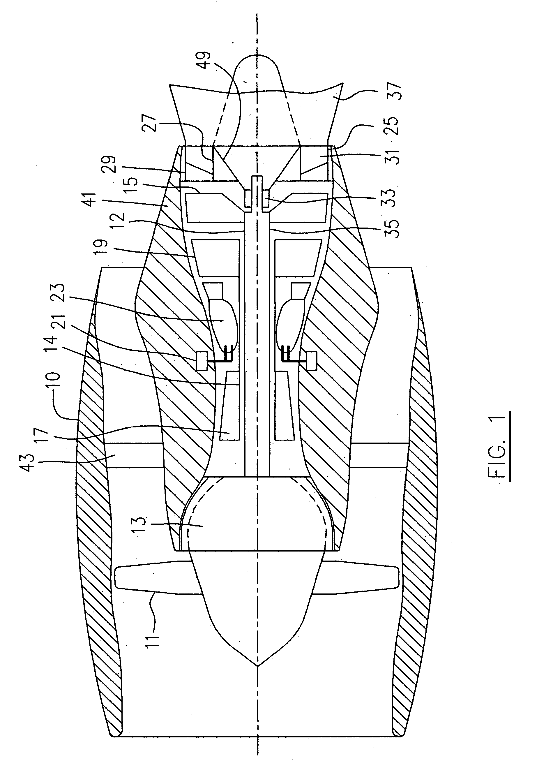
[0021] A bypass gas turbine engine seen generally in FIG. 1 includes a housing or nacelle 10, a low pressure spool assembly seen generally at 12 which includes a fan 11, low pressure compressor 13 and low pressure turbine 15, a high pressure spool assembly seen generally at 14 which includes a high pressure compressor 17, high pressure turbine 19, a burner seen generally at 23 and fuel injecting means 21.

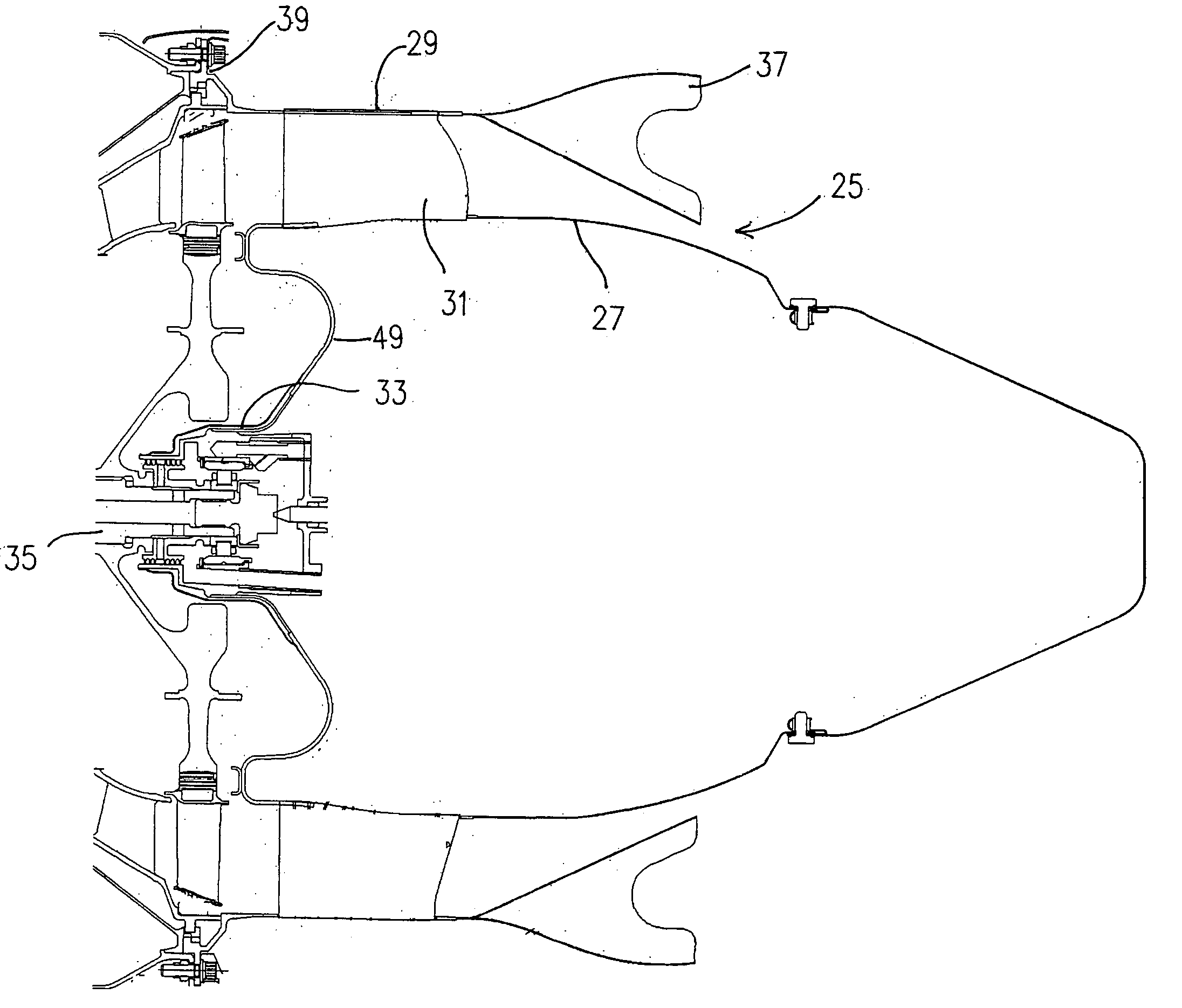
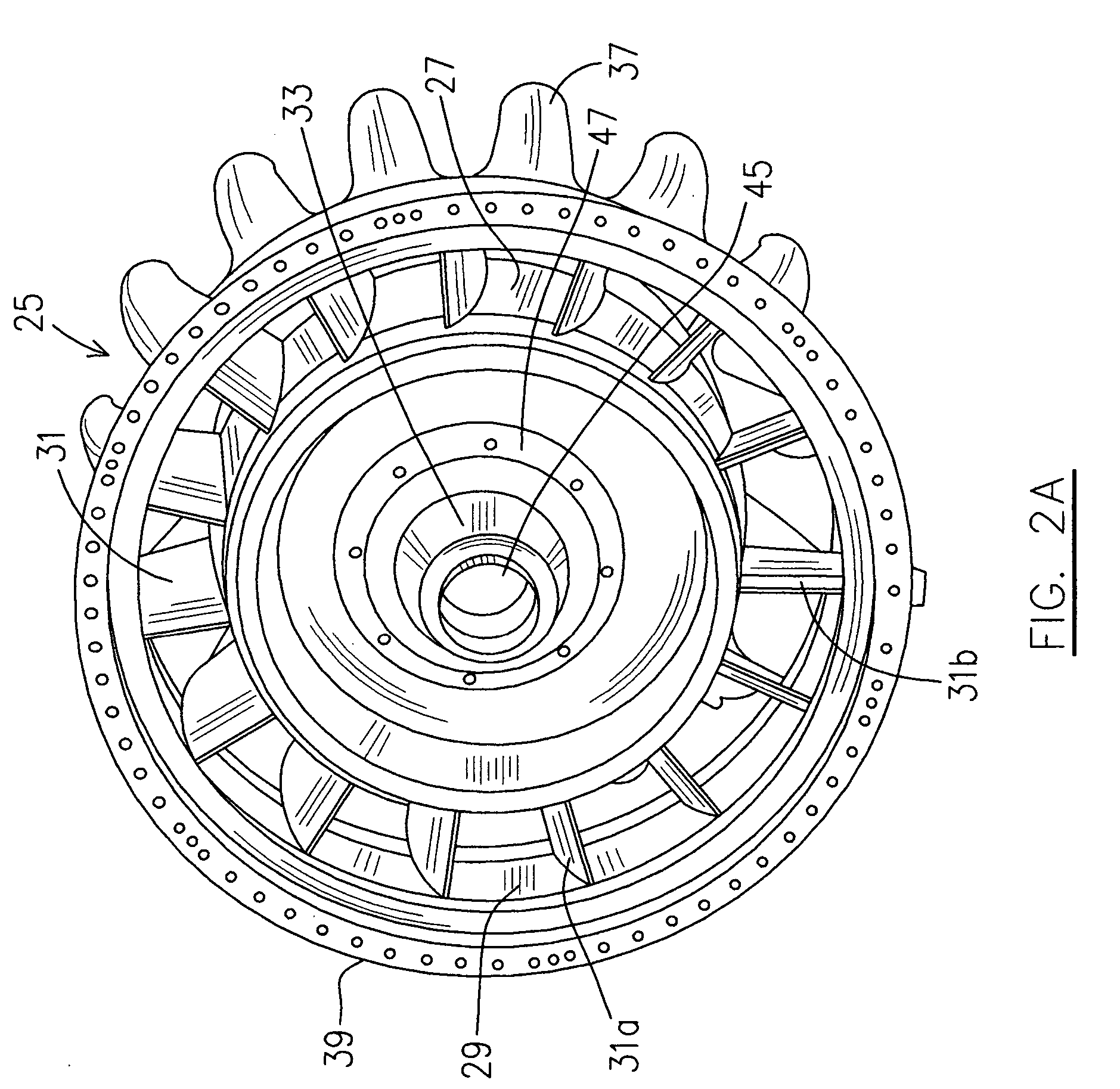
[0022] Referring to FIGS. 1 and 2A-2B, the bypass gas turbine engine further includes a turbine exhaust case 25 which as an example of the present invention, includes an annular inner case portion 27 and an annular outer case portion 29 and a plurality of airfoils 31 circumferentially spaced apart, and radially extending between the inner and outer case portions 27, 29, thereby structurally connecting same. A bearing housing 33 is co-axially connected to the inner case portion 27 for supporting an aft end of a main shaft 35 of the low pressure spool 12. Preferably, there is a mixer...


PUM

PropertyMeasurementUnit
Thicknessaaaaaaaaaa
Heightaaaaaaaaaa

Abstract

A structural turbine exhaust case of a gas turbine engine, comprises inner and outer case portions; a bearing housing connected to the inner case portion for supporting a main spool of the gas turbine engine; and a plurality of airfoils extending between the inner and outer case portions, airfoils structurally connecting the inner case portion to the outer case portion.

Description

FIELD OF THE INVENTION [0001] The present invention relates to gas turbine engines, and more particularly to a turbine exhaust case of an gas turbine engine. BACKGROUND OF THE INVENTION [0002] A “non-structural” turbine exhaust case typically used for gas turbines and is basically little more than an aerodynamic fairing, and carries no additional load other than its own weight and any aerodynamic loading effecting thereon. A “structural” turbine exhaust case on the other hand not only supports its own weight and any aerodynamic loading, but also supports a bearing housing and bearing for a main spool of the engine, typically, the low pressure spool. Present state of the art structural turbine exhaust cases, and in particular the bearing housing and the airfoils components, are made of cast components. However, cast components used in smaller airborne gas turbine engines (e.g. about 2000 lbs thrust and under) will increase the weight and thereby cost of manufacturing. Thus it would b...

Claims


Application Information

Patent Timeline
IPC IPC(8): F02K1/46
CPCB23K15/0093Y10T29/49321B23K26/28B23K2201/001F01D5/3061F01D7/00F01D9/065F01D25/162F02K1/386F02K1/48Y02T50/671Y02T50/673F05D2230/60F05D2230/232Y10T29/4932B23K15/04B23K2101/001Y02T50/60
Inventor GEKHT, EUGENEFONTAINE, MIKEJUTRAS, MARTIN
Owner PRATT & WHITNEY CANADA CORP
Why Eureka
Try Eureka