Method and system for reducing operational shock sensitivity of MEMS devices

a technology of mems devices and shock sensitivity, applied in the field of microelectromechanical systems, can solve the problems of impulses, large additional errors, and weak spring constants of mems structures, and achieve the effects of reducing the operational shock sensitivity of the mems devi

Active Publication Date: 2006-01-19
LUMENTUM OPERATIONS LLC
View PDF8 Cites 35 Cited by
  • Summary
  • Abstract
  • Description
  • Claims
  • Application Information

AI Technical Summary

Benefits of technology

[0011] In accordance with one aspect of the instant invention there is provided a method for reducing operational shock sensitivity of a MEMS device comprising: detecting a shock experienced by the MEMS device; and, altering closed-loop parameters of the MEMS device in dependence upon the detected shock such that effects of the shock are other than compensated for.
[0012] In accordance with another aspect of the instant invention there is provided a method for reducing operational shock sensitivity of a MEMS device comprising: providing a MEMS device having a MEMS structure coupled to a controller in a closed-loop configuration, the controller for providing a control signal used to drive the MEMS structure; detecting a shock experienced by the MEMS device, a magnitude of the shock being sufficient to cause the MEMS structure to resonate at its natural mechanical vibration frequency fo for a damping time td; and, upon detecting the shock, altering the control signal such that an amount the MEMS structure is driven in response to the shock is reduced.
[0013] In accordance with another aspect of the instant invention there is provided a method for reducing operational shock sensitivity of a MEMS device comprising: controlling the MEMS device using a closed-loop control circuit, the closed-loop control circuit including a movable MEMS structure, a detector for sensing a position of the MEMS structure and for providing a feedback signal related to the sensed position, and a processor for receiving the feedback signal and for providing a control signal used to control the MEMS device, the control signal determined in dependence upon the feedback signal; detecting a shock experienced by the MEMS device; and, altering the control signal in dependence upon the detected shock such that a response of the closed-loop control circuit to the shock is minimized.
[0014] In accordance with yet another aspect of the instant invention there is provided a system for reducing operational shock sensitivity of a MEMS device comprising: a closed-loop control circuit for controlling the MEMS device, the closed-loop control circuit including a movable MEMS structure, a detector for sensing a position of the MEMS structure and for providing a first feedback signal related to the sensed position, and a processor for receiving the first feedback signal and for providing a control signal used to control the MEMS device, the control signal determined in dependence upon the first feedback signal; and, a shock detector for detecting a shock experienced by the MEMS device and for generating a second feedback signal, the second feedback signal used to alter the control signal such that a response of the closed-loop control circuit to the shock is minimized.

Problems solved by technology

However, MEMS structures with weak spring constants are susceptible to undesired perturbations.
For example, mechanical shock or vibration often results in an impulse that occurs at the natural mechanical vibrational frequency of the MEMS structure.
Unfortunately, most control systems operate at bandwidths much lower in frequency than the natural mechanical frequency of the MEMS structure in order to avoid difficulties associated with lag due to mechanical inertia.
This compensation is not required, and thus introduces a large additional error due to inappropriate delayed feedback.
This additional and delayed error significantly contributes to the operational shock sensitivity of MEMS devices.

Method used


Image

  • Method and system for reducing operational shock sensitivity of MEMS devices
  • Method and system for reducing operational shock sensitivity of MEMS devices
  • Method and system for reducing operational shock sensitivity of MEMS devices

Examples


Embodiment Construction

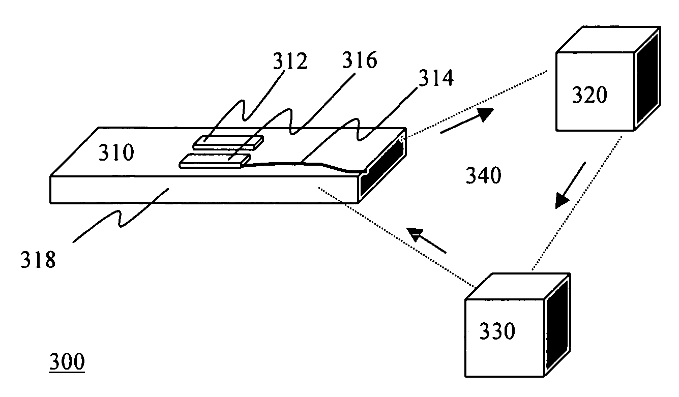
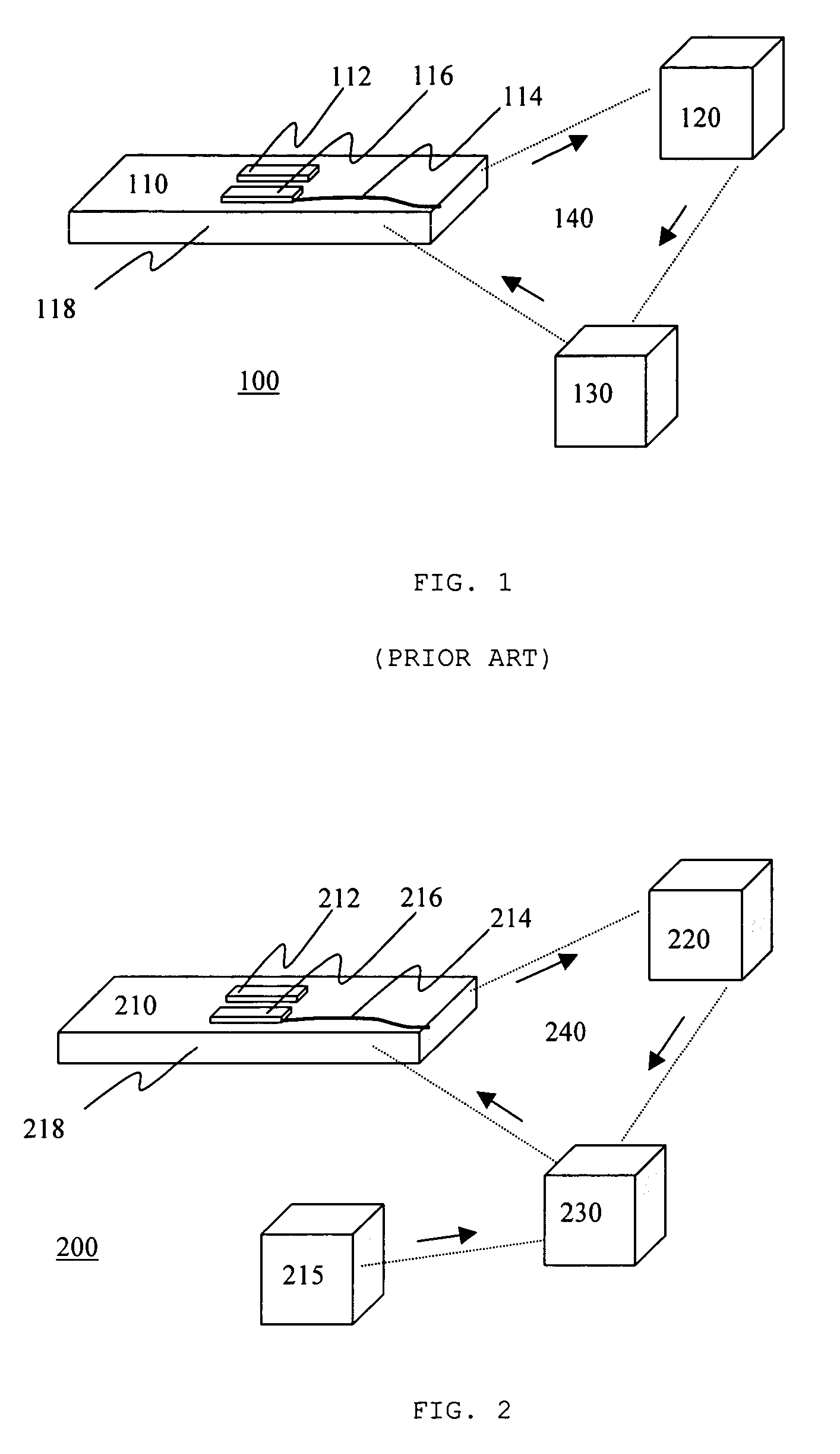
[0021] Referring to FIG. 1, there is shown a schematic diagram of a control system used in a prior art MEMS device. The control system 100 includes a MEMS structure 110, a detector 120, and a controller 130. The controller 130 is electrically connected to the MEMS structure 110 and the detector 120, such that it forms a part of the closed loop feedback circuit 140. The MEMS structure 110 has a mechanical component 112, an electrical component 114, and an actuator 116, all formed on a same substrate 118.

[0022] In operation, the controller 130 provides a control signal that drives the actuator 116, thus moving the mechanical component 112. As the mechanical component 112 moves, the detector 120 measures a parameter related to the position of the mechanical component 112, and provides a feedback signal to the controller 130. The controller 130 alters the control signal sent to the actuator 116 in dependence upon the feedback signal. Typically, the altered control signal is generated f...


PUM


Abstract

A method and system for reducing operational shock sensitivity of a MEMS device includes a closed-loop control circuit for controlling the MEMS device and a shock detector for detecting a shock experienced by the MEMS device. The closed-loop control circuit includes a movable MEMS structure, a detector for sensing a position of the MEMS structure and for providing a first feedback signal related to the sensed position, and a processor for receiving the first feedback signal and for providing a control signal used to control the MEMS device. The shock detector, which according to a preferred embodiment is the MEMS structure itself, is used for detecting the shock experienced by the MEMS device and for generating a second feedback signal, which is used to alter the control signal such that a response of the closed-loop control circuit to the shock is minimized.

Description

CROSS-REFERENCE TO RELATED APPLICATIONS [0001] This application claims the benefit of U.S. Provisional Application No. 60 / 587,992 filed Jul. 14, 2004, the contents of which are incorporated by reference herein.MICROFICHE APPENDIX [0002] Not Applicable. TECHNICAL FIELD [0003] The present application relates generally to microelectromechanical systems (MEMS) and, more particularly, to a method and system for reducing operational shock sensitivity of MEMS devices. BACKGROUND OF THE INVENTION [0004] Microelectromechanical systems (MEMS) integrate electrical and mechanical components on a single substrate, such as silicon, using microfabrication technologies. Typically, the electrical components are fabricated using integrated circuit processes, while the mechanical components are fabricated using micromachining processes that are compatible with the integrated circuit processes. [0005] MEMS devices are found in an increasing number of applications, from sensor technology, to biomedicine...

Claims


Application Information

Patent Timeline
Patent Type & Authority Applications(United States)
IPC IPC(8): G01B7/16
CPCG01P15/13G01P1/003
Inventor SCHNEIDER, DAVID
Owner LUMENTUM OPERATIONS LLC
Why Eureka
Try Eureka