Supporting element having a supporting surface for supporting a fuel feed unit, and fuel feed unit

a technology of supporting elements and fuel feed units, which is applied in the direction of positive displacement liquid engines, piston pumps, separation processes, etc., can solve the problems that the dirt particles situated at the tangential edge are not able to block the flow of fuel below the fuel feed unit, and achieve high stability, reduce the loading of the bottom of the fuel tank, and the effect of being particularly cost-effectiv

Active Publication Date: 2006-01-19
VITESCO TECH GERMANY GMBH
View PDF14 Cites 9 Cited by
  • Summary
  • Abstract
  • Description
  • Claims
  • Application Information

AI Technical Summary

Benefits of technology

[0013] The supporting element according to the invention can be manufactured particularly cost-effectively if the fastening means, the coarse filter and the curved element are manufactured as a single piece from plastic by injection molding.
[0014] The supporting element according to the invention has particularly high stability if at least one radially oriented web is guided radially inward from the curved element.
[0015] The supporting surface could be arranged exclusively on the curved element. The supporting surface is increased, according to another advantageous development of the invention, if the supporting surface is arranged on the curved element and the radially inwardly guided webs. This further reduces the loading of the bottom of the fuel tank.
[0016] The introduction of dirt into the region below the fuel feed unit is further reduced, according to another advantageous development of the invention, if at least one duct for guiding fuel into a central region below the fuel feed unit is guided over the curved element and / or is guided between two curved elements. With the duct guided over the curved element, the curved element, in the fitted state, forms a sill bearing against the bottom of the fuel tank. Fuel flowing in under the fuel feed unit has to overcome the sill, with the result that dirt particles situated at the bottom of the fuel tank are reliably retained.

Problems solved by technology

However, dirt particles situated at the tangential edge are not able to obstruct the flow of the fuel below the fuel feed unit.

Method used


Image

  • Supporting element having a supporting surface for supporting a fuel feed unit, and fuel feed unit
  • Supporting element having a supporting surface for supporting a fuel feed unit, and fuel feed unit
  • Supporting element having a supporting surface for supporting a fuel feed unit, and fuel feed unit

Examples


Embodiment Construction

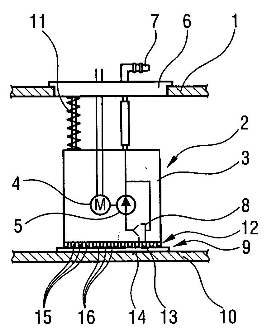
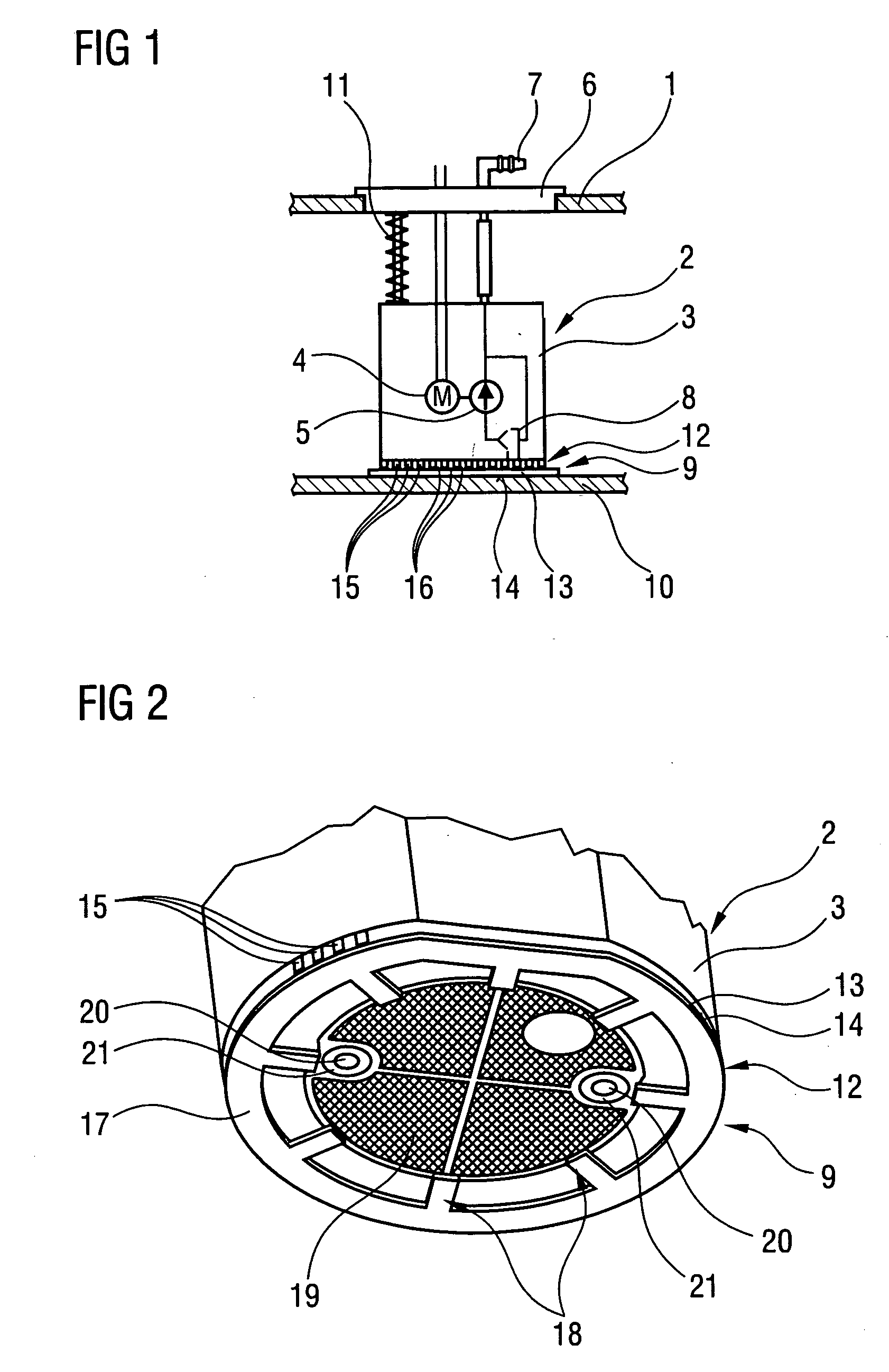
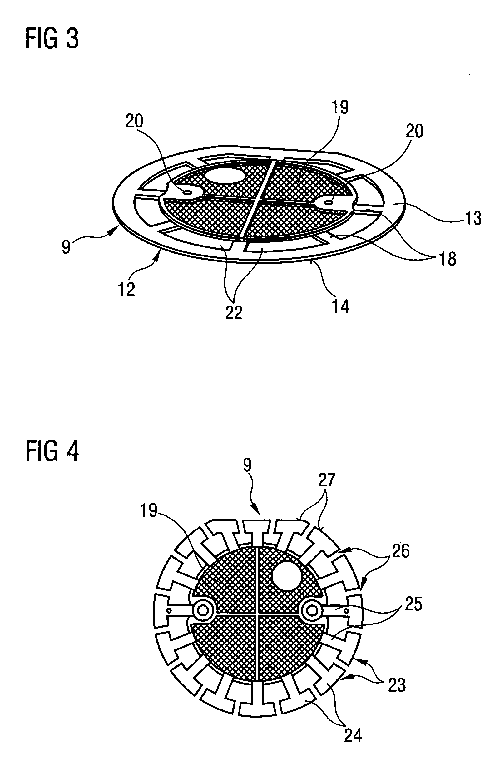
[0027]FIG. 1 schematically shows a fuel feed unit 2 arranged in a fuel tank 1. The fuel feed unit 2 has a pump stage 5 which is arranged in a surge chamber 3 and is driven by an electric motor 4. The pump stage 5 feeds fuel out of the surge chamber 3 to a connecting branch 7 arranged on a closure cover 6. A forward flow line (not illustrated) leading to an internal combustion engine can be connected to the connecting branch 7. Furthermore, the pump stage 5 feeds fuel to a suction jet pump 8 arranged in the bottom region of the surge chamber 3. The suction jet pump 8 sucks up fuel from the lower side of the surge chamber 3. The fuel feed unit 2 is supported with a supporting element 9 on the bottom 10 of the fuel tank 1. A spring element 11 prestresses the fuel feed unit 2 in the direction of the bottom 10. The supporting element 9 has a supporting foot 12 with a curved element 13 designed as an annular element. The curved element 13 therefore has an encircling edge 14 which is longe...


PUM

PropertyMeasurementUnit
widthaaaaaaaaaa
circumferenceaaaaaaaaaa
shapeaaaaaaaaaa

Abstract

A supporting element (9) for supporting a fuel feed unit (2) on the bottom of a fuel tank has a curved element (13) having a supporting surface (17). The curved element (13) is fastened to the lower side of the fuel feed unit (2) and is manufactured as a single piece with a coarse filter (19). Fuel sucked up through the coarse filter (19) is guided over the curved element (13), so that dirt particles are retained at a tangential edge (14) of the supporting element (9).

Description

BACKGROUND OF THE INVENTION [0001] The invention relates to a supporting element having a supporting surface for supporting a fuel feed unit on the bottom of a fuel tank, having at least one protruding supporting foot which is provided with the supporting surface for resting on the bottom. The invention furthermore relates to a fuel feed unit for feeding fuel out of a fuel tank of a motor vehicle. [0002] Fuel feed units of modern motor vehicles generally have a pump which is arranged in a surge chamber and feeds fuel out of the surge chamber. The pump can be a pump stage which is driven by an electric motor or can be a suction jet pump. Feed units in which a suction jet pump sucks fuel out of a surge chamber are frequently also referred to as intake units and, like the feed units with an electrically driven pump stage, are expressly mentioned if a component is referred to as a fuel feed unit. [0003] Supporting elements of this type are generally manufactured as a single piece with a...

Claims


Application Information

Patent Timeline
Patent Type & Authority Applications(United States)
IPC IPC(8): F02M37/04
CPCB60K15/077B60K2015/03453F02M37/106B60K2015/03111B60K2015/03105B60K2015/03236F02M2037/228F02M37/50Y10T137/86035
Inventor KADLER, MATTHIASMARKEFKA, KLAUS
Owner VITESCO TECH GERMANY GMBH
Why Eureka
Try Eureka